©2022 Lennox Industries Inc.
Dallas, Texas, USA
Page 1
THIS MANUAL MUST BE LEFT WITH THE
HOMEOWNER FOR FUTURE REFERENCE
General
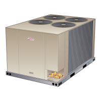
This EL17XC1 outdoor air conditioner with all-aluminum
coil is designed for use with HFC-410A refrigerant only.
This unit must be installed with an approved indoor air han-
dler or coil. For AHRI Certied system match-ups and ex-
panded ratings, visit www.LennoxPros.com.
These instructions are intended as a general guide and do
not supersede local codes in any way. Consult authorities
having jurisdiction before installation.
NOTICE!
Charging information is given on the charging
procedure sticker on the unit access panel. For more in-
depth information, consult the Installation and Service
Procedures manual on LennoxPros.com or through the
Technical Support department at 800-453-6669.
INSTALLATION
INSTRUCTIONS
AIR CONDITIONER
508253-01
3/2022
Elite
®
Series EL17XC1 Units
WARNING
Improper installation, adjustment, alteration, service
or maintenance can cause property damage, personal
injury or loss of life. Installation and service must be
performed by a licensed professional HVAC installer or
equivalent, or service agency.
CAUTION
As with any mechanical equipment, contact with sharp
sheet metal edges can result in personal injury. Take
care while handling this equipment and wear gloves and
protective clothing.
IMPORTANT: Special procedures are required for clean-
ing the all-aluminum coil in this unit. See page 15 in this
instruction for information.
STEP 1 – SETTING THE UNIT – Clearances
See
NOTES
See NOTES
NOTES:
Service clearance of 30 in. (762 mm) must be maintained on one of
the sides adjacent to the control box.
Clearance to one of the other three sides must be 36 in (914 mm).
Clearance to one of the remaining two sides may be 12 in. (305mm)
and the final side may be 6 in.(152 mm).
A clearance of 24 in. (610 mm) must be maintained between two units.
48 in. (1219 mm) clearance required on top of unit.
See
NOTES
See NOTES
Control
Box
NOTICE: Specific applications may require adjustment of the listed installation clearances to provide protection for
the unit from physical damage or to avoid conditions which limit operating efficiency. (Example: Clearances may
have to be increased to prevent snow or ice from falling on the top of the unit. Additional clearances may also be
required to prevent air recirculation when the unit is installed under a deck or in another tight space.)
FIGURE 1