Page 1
THIS MANUAL MUST BE LEFT WITH THE
HOMEOWNER FOR FUTURE REFERENCE
WARNING
Improper installation, adjustment, alteration, service
or maintenance can cause property damage, personal
injury or loss of life. Installation and service must be
performed by a licensed professional HVAC installer or
equivalent, service agency, or the gas supplier.
CAUTION
As with any mechanical equipment, contact with sharp
sheet metal edges can result in personal injury. Take
care while handling this equipment and wear gloves and
protective clothing.
Shipping and Packing List
Package 1 of 1 contains:
1 – Assembled electric heat section
1 – Bag assembly containing the following:
6 – Screws
1 – Wiring diagram
Circuit breaker cover - 1 each
1 – Transformer (575V, 3-phase, 60Hz only)
1 – Fuse block extension plate (460V, 3-phase, 60Hz and
575V, 3-phase, 60Hz only)
2 – Adhesive-backed foam seals
1 – Circuit breaker cover
Check equipment for shipping damage; if found, immedi-
ately contact the last carrier.
INSTALLATION
INSTRUCTIONS
ELECTRIC HEAT SECTIONS
507413-02
7/2019
ECB29 Series Units
WARNING
Electric shock hazard! - Disconnect all power
supplies before servicing.
Replace all parts and panels before
operating.
Failure to do so can result in death or
electrical shock.
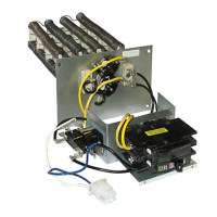
Electric Heat Section
The ECB29 series electric heat section provides eld-in-
stalled electric heat for various air handler units. These
electric heat sections are available in either single- or
three-phase. Single-phase heat sections are equipped
with either terminal blocks or circuit breakers.
Refer to the model-specic air handler product specica-
tion bulletin for heat section applications.
General Information
These instructions are a general guide and do not su-
persede local codes. Local authorities having jurisdiction
should be consulted before installation. Read these in-
structions thoroughly before starting installation.
Be sure to disconnect all power to the unit before you in-
stall and service this equipment. Use proper tools and pro-
tective equipment during installation and service.
Installation of air handler with or without optional electric
heat must conform with standards in the National Fire
Protection Association (NFPA) Standard for Installation of
Air Conditioning and Ventilation Systems NFPA No. 90A,
and Standard for Installation of Resident Type Warm Air
Heating and Air Conditioning System, No. 90B, the man-
ufacturer’s installation instructions, and local municipal
building codes.