EasyManua.ls Logo

Lennox ECB29-10CB - User Manual

Lennox ECB29-10CB
11 pages
Print Icon
To Next Page IconTo Next Page
Loading...
Page 1
THIS MANUAL MUST BE LEFT WITH THE
HOMEOWNER FOR FUTURE REFERENCE
WARNING
Improper installation, adjustment, alteration, service
or maintenance can cause property damage, personal
injury or loss of life. Installation and service must be
performed by a licensed professional HVAC installer or
equivalent, service agency, or the gas supplier.
CAUTION
As with any mechanical equipment, contact with sharp
sheet metal edges can result in personal injury. Take
care while handling this equipment and wear gloves and
protective clothing.
Shipping and Packing List
Package 1 of 1 contains:
1 – Assembled electric heat section
1 – Bag assembly containing the following:
6 – Screws
1 – Wiring diagram
Circuit breaker cover - 1 each
1 – Transformer (575V, 3-phase, 60Hz only)
1 – Fuse block extension plate (460V, 3-phase, 60Hz and
575V, 3-phase, 60Hz only)
2 – Adhesive-backed foam seals
1 – Circuit breaker cover
Check equipment for shipping damage; if found, immedi-
ately contact the last carrier.
INSTALLATION
INSTRUCTIONS
ELECTRIC HEAT SECTIONS
507413-02
7/2019
ECB29 Series Units
WARNING
Electric shock hazard! - Disconnect all power
supplies before servicing.
Replace all parts and panels before
operating.
Failure to do so can result in death or
electrical shock.
Electric Heat Section
The ECB29 series electric heat section provides eld-in-
stalled electric heat for various air handler units. These
electric heat sections are available in either single- or
three-phase. Single-phase heat sections are equipped
with either terminal blocks or circuit breakers.
Refer to the model-specic air handler product specica-
tion bulletin for heat section applications.
General Information
These instructions are a general guide and do not su-
persede local codes. Local authorities having jurisdiction
should be consulted before installation. Read these in-
structions thoroughly before starting installation.
Be sure to disconnect all power to the unit before you in-
stall and service this equipment. Use proper tools and pro-
tective equipment during installation and service.
Installation of air handler with or without optional electric
heat must conform with standards in the National Fire
Protection Association (NFPA) Standard for Installation of
Air Conditioning and Ventilation Systems NFPA No. 90A,
and Standard for Installation of Resident Type Warm Air
Heating and Air Conditioning System, No. 90B, the man-
ufacturer’s installation instructions, and local municipal
building codes.
Question and Answer IconNeed help?

Do you have a question about the Lennox ECB29-10CB and is the answer not in the manual?

Summary

INSTALLATION INSTRUCTIONS

Electric Heat Section Overview

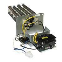
Provides field-installed electric heat for air handler units.

Heat Section Installation Procedures

Pre-Installation Checks

Check unit rating plate, power availability, and duct clearances.

460 V 3-Ton Air Handler Cabinet Mods

Necessary modifications for specific models in 460V, 3-ton air handlers.

Circuit Breaker Installation Steps

Mounting the Circuit Breaker

Secure circuit breaker onto the air handler deck flange with screws.

Circuit Breaker Cover Installation

Installing the Circuit Breaker Cover

Clean surface, apply seal, and position breaker cover for airtight seal.

Electrical Connection Guidelines

Wiring connections for air handler units, using copper conductors only.

Unit Start-Up Procedures

Unit Start-Up Steps

Steps for starting up the unit after installation.

Overview

The provided manual describes the installation and features of ECB29 Series Electric Heat Sections, designed for use with various air handler units. These heat sections provide supplemental electric heating for HVAC systems.

Function Description:

The ECB29 series electric heat sections are field-installable components that integrate with air handler units to provide electric heating. They are available in both single-phase and three-phase configurations. Single-phase units are equipped with either terminal blocks or circuit breakers, while three-phase units may utilize fuse blocks. The heat sections are designed to be installed within the air handler's vestibule panel, requiring specific knockouts to be removed for proper fitment, especially for higher wattage units (20kW or 25kW). Once installed, they connect to the air handler's electrical system to provide heat, controlled by the thermostat and integrated with the blower operation. The manual emphasizes the importance of proper electrical connections and cabinet modifications to ensure safe and efficient operation.

Important Technical Specifications:

  • Voltage: Available in various voltages, including 208-240V (single-phase, 60Hz), 460V (3-phase, 60Hz), and 575V (3-phase, 60Hz).
  • Phases: Available in single-phase and three-phase configurations.
  • Wattage: Heat sections are available in various wattages, with specific instructions for 20kW and 25kW units requiring extended width knockouts.
  • Circuit Protection: Single-phase units come with either terminal blocks or circuit breakers. Three-phase units (460V and 575V) may use fuse blocks, with a transformer provided for 575V units to step down to 460V for the air handler motor and transformer.
  • Conductors: Requires copper conductors only.
  • Blower Speed: The minimum blower setting for any air handler size with any heat section in any application is HIGH.
  • Thermostat Heat Anticipator Setting: 0.4 amps (for electric heat).

Usage Features:

  • Field-Installable: Designed for easy integration into existing or new air handler units.
  • Compatibility: Refer to model-specific air handler product specification bulletins for heat section applications.
  • Two-Stage Thermostat Support: Instructions are provided for connecting two-stage thermostats, including removing jumpers between W2 and R terminals and connecting the second-stage heat bulb lead to W2.
  • Outdoor Thermostat Support: Instructions for connecting outdoor thermostats, involving removing jumpers between W2 and R terminals and connecting leads to W2 and R.
  • Blower Speed Adjustment: The blower speed must be adjusted according to the size of the electric heat and air handler unit, with a minimum HIGH setting for all heat sections.
  • Wiring Diagrams: Comprehensive wiring diagrams are provided for various configurations, including cooling and heat pump applications, and for different motor types (Constant Torque and PSC, Non-Communicating Motors). A cross-reference table links specific electric heat section models to their corresponding wiring diagrams.

Maintenance Features:

  • Safety First: Emphasizes disconnecting all power supplies before servicing to prevent electric shock.
  • Professional Installation/Service: Installation, adjustment, alteration, service, or maintenance must be performed by a licensed professional HVAC installer or equivalent, service agency, or the gas supplier.
  • Grounding: Unit must be properly grounded in accordance with national and local codes.
  • Access Panels: Requires removal and replacement of air handler access panels for installation and service.
  • Circuit Breaker Cover: For units installed in unconditioned spaces, a provided circuit breaker cover must be installed using isopropyl alcohol for cleaning and a bead of clear silicone to ensure an airtight seal. This prevents warm, moist air from causing condensation on electrical components.
  • Regular Checks: After installation, users are instructed to replace the access cover, restore power, set the thermostat anticipator, affix the wiring diagram sticker, set the thermostat above room temperature, check for normal operation, and finally set the thermostat to the desired setting.
  • Sharp Edges Caution: Users are advised to take care while handling the equipment and wear gloves and protective clothing due to sharp sheet metal edges.

The manual also includes specific instructions for cabinet modifications required for certain 460V, 3-ton models, where tabs on the air handler must be removed to allow proper installation of the electric heat section. Detailed steps for installing circuit breakers, including rotation for downflow applications, and securing patch plates and seals are also provided to ensure proper and safe operation.

Lennox ECB29-10CB Specifications

General IconGeneral
BrandLennox
ModelECB29-10CB
CategoryAir Conditioner
LanguageEnglish

Related product manuals