Page 3
WARNING
Electric Shock Hazard. Can cause injury or
death. Unit must be properly grounded in
accordance with national and local codes.
Line voltage is present at all components
when unit is not in operation on units with
single-pole contactors. Disconnect all remote
electric power supplies before opening
access panel. Unit may have multiple power
supplies.
Circuit Breaker Installation
1 - Install the circuit breaker on the air handler deck
ange. Use the provided six screws to secure the
circuit breaker (see gure 3).
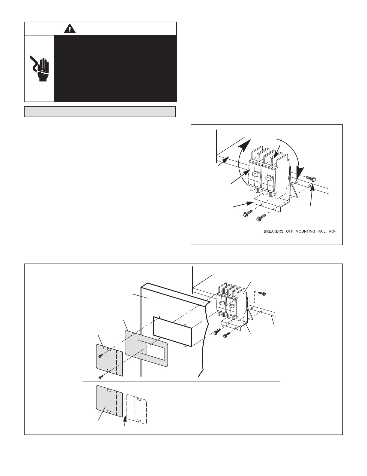
NOTE – When applied in the downow position, the cir-
cuit breakers must be rotated to the UP position. See
gure 3 and follow the procedure below:
A - Disconnect power to the unit if present.
B - Remove the screw and slide the breakers o the
mounting rail.
NOTE – You may need to remove the wire tie closest to
the circuit breaker to allow rotation.
C - Rotate the circuit breaker 180 degrees.
D - Slide the circuit breaker back on the rail and secure
in place with previously removed screw.
2 - The air handler access panels are factory supplied.
There is a patch plate over the circuit breaker opening.
Remove the circuit breaker patch plate from the air
handler access panel. See gure 4.
3 - Replace the air handler access door.
4 - Choose the appropriately sized adhesive-backed
circuit breaker seal and remove any perforated
sections (if needed). Apply the seal to the outside of
the air handler access panel so that the seal is snug
around the circuit breakers.
5 - Break the patch plate for the specic size of electric
heat section that you are installing. Discard the
unused piece of patch plate (see gures 5 and 6).
6 - Secure the patch plate on the air handler access
door.
IN DOWNFLOW APPLICATIONS, CIRCUIT BREAKERS
MUST BE ROTATED 180º TO THE UP POSITION.
REMOVE THE SCREW AND SLIDE THE
TATE BREAKERS 180º AND SLIDE BACK
ON RAIL. SECURE WITH SCREW.
CIRCUIT
BREAKER
BRACKET
CIRCUIT
BREAKERS
IR HANDLER
DECK
CIRCUIT BREAKER
MOUNTING SCREW
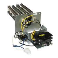
FIGURE 3. Electric Heat Section with Circuit Breakers
CIRCUIT BREAKER
BRACKET
CIRCUIT
BREAKERS
AIR HANDLER
DECK
PATCH PLATE
CIRCUIT
BREAKER
SEAL
AIR HANDLER
ACCESS PANEL
DISCARD
PATCH PLATE
NOTE — IT IS HIGHLY RECOMMENDED TO USE THE
CIRCUIT BREAKER COVER (ORDERED SEPARATELY).
ORDER CATALOG # 82W01.
FIGURE 4. Circuit Breaker Seal and Patch Plate Installation