EasyManua.ls Logo

Lennox Elite EL17XC1 Series User Manual

Lennox Elite EL17XC1 Series
16 pages
To Next Page IconTo Next Page
Page #1 background imageLoading...
Page #1 background image
©2022 Lennox Industries Inc.
Dallas, Texas, USA
Page 1
THIS MANUAL MUST BE LEFT WITH THE
HOMEOWNER FOR FUTURE REFERENCE
General
This EL17XC1 outdoor air conditioner with all-aluminum
coil is designed for use with HFC-410A refrigerant only.
This unit must be installed with an approved indoor air han-
dler or coil. For AHRI Certied system match-ups and ex-
panded ratings, visit www.LennoxPros.com.
These instructions are intended as a general guide and do
not supersede local codes in any way. Consult authorities
having jurisdiction before installation.
NOTICE!
Charging information is given on the charging
procedure sticker on the unit access panel. For more in-
depth information, consult the Installation and Service
Procedures manual on LennoxPros.com or through the
Technical Support department at 800-453-6669.
INSTALLATION
INSTRUCTIONS
AIR CONDITIONER
508253-01
3/2022
Elite
®
Series EL17XC1 Units
WARNING
Improper installation, adjustment, alteration, service
or maintenance can cause property damage, personal
injury or loss of life. Installation and service must be
performed by a licensed professional HVAC installer or
equivalent, or service agency.
CAUTION
As with any mechanical equipment, contact with sharp
sheet metal edges can result in personal injury. Take
care while handling this equipment and wear gloves and
protective clothing.
IMPORTANT: Special procedures are required for clean-
ing the all-aluminum coil in this unit. See page 15 in this
instruction for information.
STEP 1 – SETTING THE UNIT – Clearances
See
NOTES
See NOTES
NOTES:
Service clearance of 30 in. (762 mm) must be maintained on one of
the sides adjacent to the control box.
Clearance to one of the other three sides must be 36 in (914 mm).
Clearance to one of the remaining two sides may be 12 in. (305mm)
and the final side may be 6 in.(152 mm).
A clearance of 24 in. (610 mm) must be maintained between two units.
48 in. (1219 mm) clearance required on top of unit.
See
NOTES
See NOTES
Control
Box
NOTICE: Specific applications may require adjustment of the listed installation clearances to provide protection for
the unit from physical damage or to avoid conditions which limit operating efficiency. (Example: Clearances may
have to be increased to prevent snow or ice from falling on the top of the unit. Additional clearances may also be
required to prevent air recirculation when the unit is installed under a deck or in another tight space.)
FIGURE 1
Question and Answer IconNeed help?

Do you have a question about the Lennox Elite EL17XC1 Series and is the answer not in the manual?
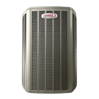
Lennox Elite EL17XC1 Series Specifications

General IconGeneral
Compressor TypeSingle-Stage
RefrigerantR-410A
Energy Star CertifiedYes
SEER Rating17.00
Warranty10-Year Limited Warranty on covered components

Summary

General

STEP 1 – SETTING THE UNIT – Clearances

UNIT DIMENSIONS – INCHES (MM)

EL17XC1 Dimensions Table

Table listing dimensions for various EL17XC1 models in inches and millimeters.

STEP 1 – SETTING THE UNIT (Continued) – Unit Placement

Elevated Slab Mounting

Instructions for mounting the unit on an elevated slab using feet extenders.

Stabilizing Unit on Uneven Surfaces

Guidance on securing the unit on uneven or unstable surfaces.

Slab Mounting

Procedures for installing the unit on a concrete slab.

STEP 2 – REFRIGERANT PIPING – Flushing Existing Line Set & Indoor Coil

Flushing Procedure

Instructions for flushing existing refrigerant lines and indoor coils before installation.

Refrigerant Line Set Sizing

Table detailing recommended refrigerant line set sizes based on model and length.

STEP 2 – REFRIGERANT PIPING – Removing Existing Indoor Metering Device

Fixed Orifice Removal

Procedure for removing a fixed orifice metering device from the indoor coil.

Expansion Valve Removal

Procedure for removing an existing expansion valve from the indoor coil.

STEP 2 – REFRIGERANT PIPING – Brazing Procedures

Cut and Debur Lines

Instructions on preparing refrigerant lines for brazing, including cutting and deburring.

Cap and Core Removal

Steps for removing service valve caps and cores before brazing.

Attach Manifold Gauge Set

Guidance on connecting a manifold gauge set for brazing operations.

STEP 2 – REFRIGERANT PIPING – Brazing Procedures (Continued)

Wrap Service Valves

How to wrap service valves with water-saturated cloths to protect them during brazing.

Flow Nitrogen

Procedure for flowing nitrogen through the system during brazing for protection.

Braze Line Set

Instructions for brazing the refrigerant line set to the service valves.

STEP 2 – REFRIGERANT PIPING – Install Indoor Expansion Valve

Indoor Expansion Valve Installation

Detailed steps for installing the expansion valve unit at the indoor coil.

Sensing Bulb Installation

Guidance on correctly installing the sensing bulb for the expansion valve.

Equalizer Line Installation

Instructions for connecting the equalizer line to the expansion valve assembly.

STEP 3 - LEAK TEST AND EVACUATION

Connect Gauge Set

Procedure for connecting the manifold gauge set for leak testing with HFC-410A.

Test for Leaks

Steps to test the system for leaks using HFC-410A and nitrogen.

STEP 3 – LEAK TEST AND EVACUATION (Continued)

Connect Gauge Set for Evacuation

Connecting the gauge set, micron gauge, and vacuum pump for system evacuation.

Evacuate the System

Detailed procedure for evacuating the refrigerant lines and indoor unit to a specific micron level.

STEP 4 – ELECTRICAL – Circuit Sizing and Wire Routing

Size Circuit and Install Service Disconnect Switch

Guidance on sizing electrical circuits and installing the disconnect switch.

Install Thermostat

Instructions for installing the room thermostat at the correct location.

Unit Low Voltage Wiring

24VAC Control Wiring Diagrams (Field Installed)

STEP 5 - UNIT START-UP

Pre-Start Up Checks

Essential checks to perform before starting the unit for the first time.

Operating Manifold Gauge Set and Service Valves

How to operate and use manifold gauge sets and service valves.

Torque Requirements

Table listing recommended torque values for various fasteners.

Checking and Adding System Charge

Refrigerant Charge per Line Set Length

Table for calculating additional refrigerant charge based on line set length.

Homeowners Information

Professional Maintenance

Outdoor Unit Checks

List of inspection and maintenance tasks for the outdoor unit.

Indoor Unit Checks

List of inspection and maintenance tasks for the indoor unit.

General System Test

Procedures for performing a general system test with the unit operating.

EL17XC1 Start-Up and Performance Checklist

Cooling Mode Performance Checks

Checklist items for verifying performance during cooling mode operation.

Related product manuals