Page 6
506101−01 07/09
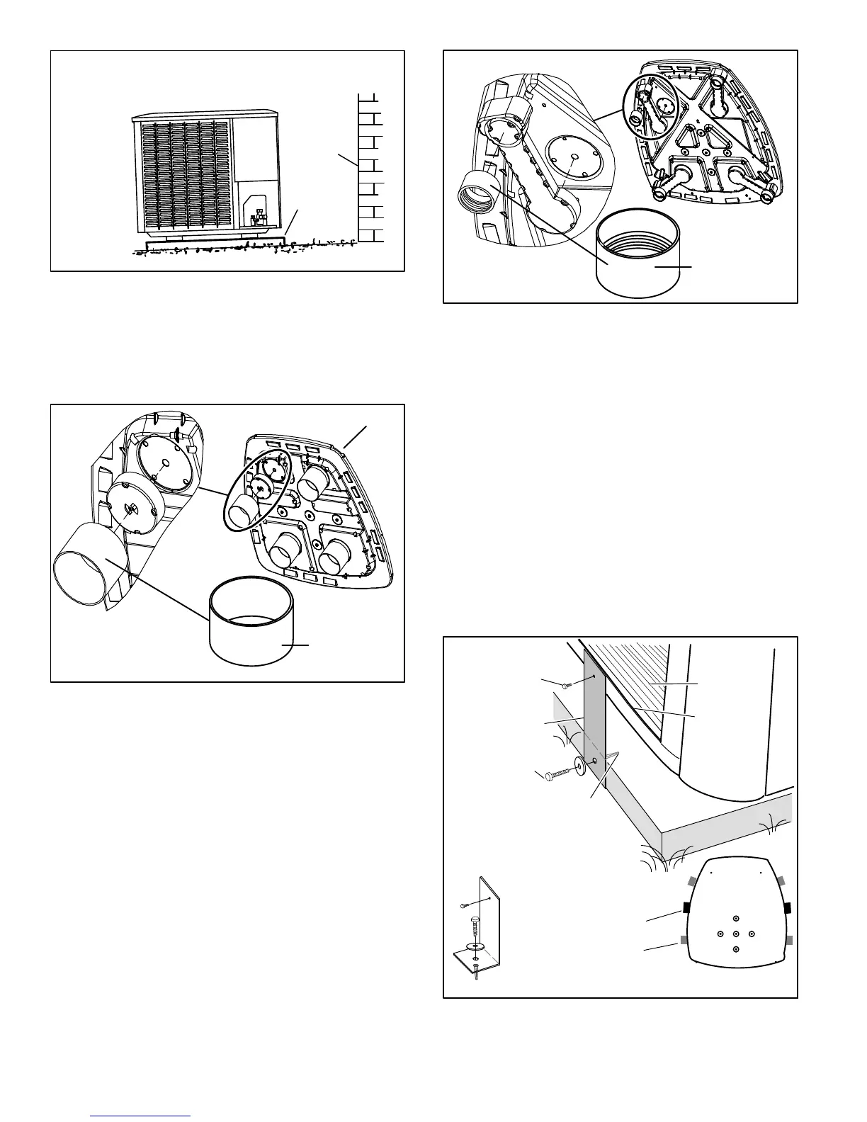
INSTALL UNIT LEVEL OR, IF ON A SLOPE, MAINTAIN SLOPE TOLERANCE
OF 2 DEGREES (OR 2 INCHES PER 5 FEET [50 MM PER 1.5 M]) AWAY FROM
BUILDING STRUCTURE.
MOUNTING
SLAB
BUILDING
STRUCTURE
GROUND LEVEL
Figure 8. Slab Mounting at Ground Level
ELEVATING THE UNIT (SMALL−BASE UNITS)
If additional elevation is necessary, raise the unit by
extending the length of the unit support feet. This may be
done by cutting four equal true−cut lengths of Schedule
(SCH) 40, 4" (101.6mm) piping to the height required as
illustrated in figure 9.
LEG DETAIL
BASE
4" (101.6MM)
SCH 40 PIPING
Figure 9. Elevated Slab Mounting using Feet
Extenders (Small Base Units)
NOTE − Keep the height of extenders short enough to
ensure a sturdy installation. If it is necessary to extend
further, consider a different type of field−fabricated
framework that is sturdy enough for greater heights.
The inside diameter of the 4" (101.6mm) piping is
approximately 0.25" (6.35mm) greater than the
pre−installed feet on the unit. Devise a shim that will take up
the space and hold the extenders onto the feet during this
procedure. Small strips of 0.125" (3.175mm) thick
adhesive foam may be used. One or two small 1"
(25.4mm) square strips should be adequate to hold the
extender in place.
ELEVATING THE UNIT (LARGER−BASE UNITS)
Unlike the small−base units which use round support feet,
the larger−base units are outfitted with elongated support
feet as illustrated in figure 10 which uses a similar method
for elevating the unit.
LEG DETAIL
BASE
2" (50.8MM) SCH 40
FEMALE THREADED
ADAPTER
Figure 10. Elevated Slab Mounting using
Feet Extenders (Larger Base Units)
If additional elevation is necessary, raise the unit by
extending the length of the unit support feet. This may be
achieved by using a 2" SCH 40 female threaded adapter.
The specified coupling will fit snuggly into the recessed
portion of the feet. Use additional 2" SCH 40 male threaded
adaptors which can be threaded into the female threaded
adaptors to make additional adjustments to the level of the
unit.
NOTE − Keep the height of extenders short enough to
ensure a sturdy installation. If it is necessary to extend
further, consider a different type of field−fabricated
framework that is sturdy enough for greater heights.
STABILIZING UNIT ON UNEVEN SURFACES
To help stabilize an outdoor unit, some installations may
require strapping the unit to the pad using brackets and
anchors commonly available in the marketplace.
ONE BRACKET PER SIDE (MIN.); FOR EXTRA STABILITY, 2
BRACKETS PER SIDE, 2" FROM EACH CORNER.
CONCRETE SLAB − USE PLASTIC
PLASTIC ANCHOR (HOLE DRILL
1/4")PLASTIC SLAB − NO PLASTIC
ANCHOR (HOLE DRILL 1/8")
COIL
BASE PAN
CORNER POST
STABILIZING
BRACKET (18 GAUGE
METAL − 2" WIDTH;
HEIGHT AS REQ’D)
Slab Side Mounting
#10 1/2" LONG SELF−
DRILLING SHEET
METAL SCREWS
#10 1−1/4" LONG
HEX HD SCREW
AND FLATWASHER
MINIMUM 1
PER SIDE
STABILIZING BRACKET (18
GAUGE METAL − 2" WIDTH;
HEIGHT AS REQ’D); BEND
TO FORM RIGHT ANGLE
FOR EXTRA
STABILITY
Deck Top Mounting
Figure 11. Installing Stabilizer Brackets

 Loading...