Page 18
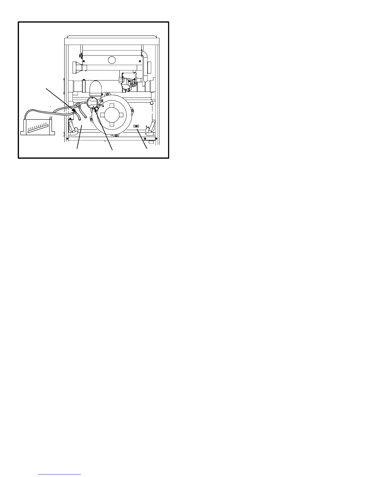
FIGURE 17
CAI & COLD END HEADER BOX ASSEMBLY
Install tee’s in the
negative line and
positive line then
connect hoses to
manometer.
prove switch
orifice size
cold end header box
+
−
4 − Operate unit and observe draft gauge reading. Read-
ings will change as heat exchanger warms.
a. Take one reading immediately after start-up.
b. Take a second reading after unit has reached steady
state (approximately 5 minutes). This will be the pres-
sure differential.
The pressure differential should be greater
than those listed in table 9.
5 − Remove thermostat demand and allow to cycle off.
6 − Remove manometer and tee’s. Reinstall combustion air
sensing hoses to the prove switch.
D−Blower Compartment
Blower motor (B3) and capacitor (C4), are located in the
blower compartment. The blower compartment can be ac-
cessed by removing the blower access panel.
1.Blower Motor (B3) and Capacitor (C4)
All G43UF units use single−phase direct−drive blower mo-
tors. All motors are 120V permanent split capacitor motors
to ensure maximum efficiency. See SPECIFICATIONS table
at the front of this manual for more detail. See motor name-
plate for capacitor ratings.

 Loading...