Page 23
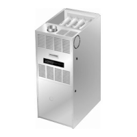
FIGURE 19
TYPICAL EXHAUST PIPE CONNECTIONS AND CONDENSATE TRAP INSTALLATION
IN UPFLOW DIRECT OR NON-DIRECT VENT APPLICATIONS
(Right-Hand Exit)
CONDENSATE
TRAP
(Must be installed
on same side as
exhaust piping)
VENT PLUG
(Must be
glued in
place)
PLUG
*2" diameter street elbow provided.
**3" diameter reducing elbow provided.
2”
2”
2”
2”
2”
2−1/2",
3", OR
4"
G43UF−045, 070
or 090 with
2−1/2", 3", or 4"
vent pipe
G43UF−135 with
3" OR 4" vent pipe
3"**
3"
REDUCER
(use only if
4" pipe is
required)
4"
2”
G43UF−110−1, −2, −3 with
2−1/2", 3", OR 4" vent pipe
2"*
2"***
TRANSITION
2−1/2",
3", OR
4"
***Limit pipe length to 2".
G43UF-1 10 with
2” vent pipe
2”*
TRANSITION
Exhaust Piping
NOTE − A 2" diameter street ell is strapped to the blower
deck of 48C−110 and 60C−110 units. Street ell must be
glued directly into the unit flue collar. See figure 19. A 3" to
2" reducing ell is strapped to the blower deck of the
60D−135 units. The reducing ell must be
glued directly into
the unit flue collar.
1. Choose the appropriate side for venting. Glue the
field−provided exhaust vent pipe (or provided street
ell) to the flue collar. All cement joints should be made
according to the specifications outlined in ASTM D
2855. Refer to pipe and fittings specifications and glu-
ing procedures.
IMPORTANT
Exhaust piping and condensate trap must be
installed on the same side of the unit.
2. All horizontal runs of exhaust pipe must slope back to-
ward unit. A minimum of 1/4" (6mm) drop for each 12"
(305mm) of horizontal run is mandatory for drainage.
Horizontal runs of exhaust piping must be supported ev-
ery 5 feet (1.52m) using hangers.
NOTE − Exhaust piping should be checked carefully to
make sure there are no sags or low spots.
3. On the opposite side of the cabinet, glue the provided
2" vent plug into the unused flue collar.
4. Route piping to outside of structure. Continue with
installation following instructions given in piping ter-
mination section.
CAUTION
Do not discharge exhaust into an existing stack or
stack that also serves another gas appliance. If verti-
cal discharge through an existing unused stack is re-
quired, insert PVC pipe inside the stack until the end
is even with the top or outlet end of the metal stack.
CAUTION
The exhaust vent pipe operates under positive pres-
sure and must be completely sealed to prevent leak-
age of combustion products into the living space.
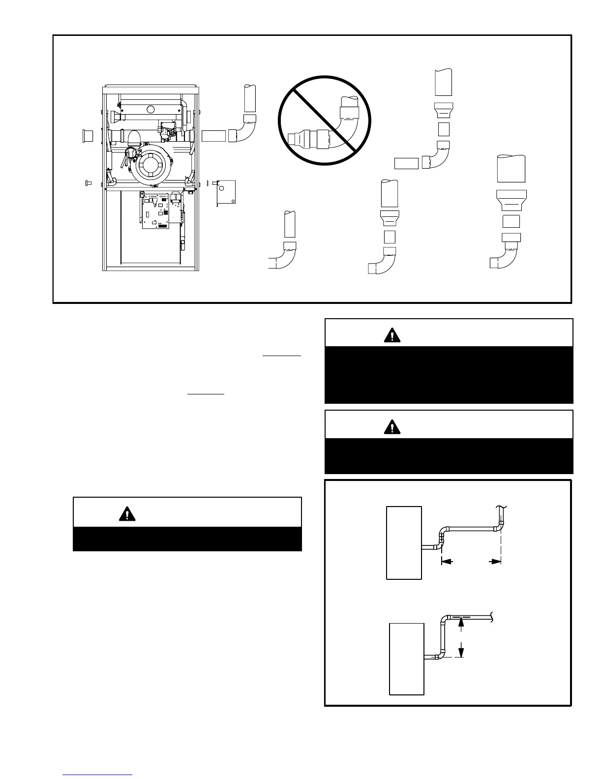
FIGURE 20
Exhaust Pipe Offset
12" Min.
12" Min.
Upflow Application
Rooftop Termination
Upflow Application
Side Wall Termination

 Loading...