Page 51
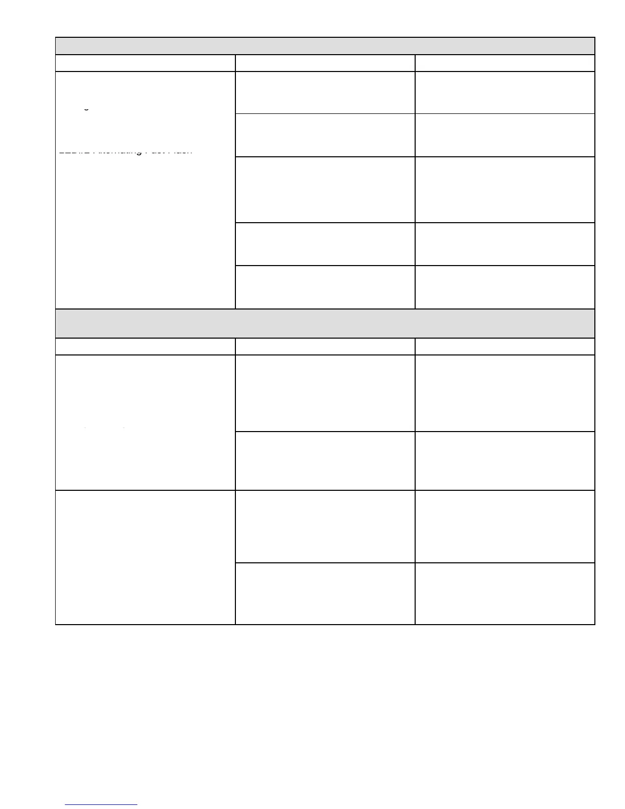
PROBLEM 1: UNIT FAILS TO OPERATE IN THE COOLING, HEATING, OR CONTINUOUS FAN MODE
Condition Possible Cause Corrective Action / Comments
1.5
− Diagnostic lights flash the improper
main ground.
1.5.1
Improper ground to the unit.
ACTION 1 − Check that the unit is properly
ground.
ACTION 2 − Install a proper main ground to the
unit
LED#1−Alternating Fast Flash*
LED#2−Alternating Fast Flash*
1.5.2
4−Pin connector is improperly at-
tached to the circuit board.
ACTION 1 − Check 4−pin connector for proper
installation. Correctly insert connector into con-
trol.
1.5.3
Line voltage is below 75V
Board 32M88
Line voltage is below 90V
Board 78M47, 100973−01
ACTION 1 − Check that the line voltage is correct.
Determine cause of voltage drop and supply cor-
rect voltage to the control.
1.5.4
Open ignitor circuit.
Board 32M88
ACTION 1 − Check for correct wiring and loose
connections in the ignitor circuit. Check mult−plug
connections for correct installation.
1.5.5
Broken or failed ignitor.
Board 32M88
ACTION 1 − Unplug ignitor and read resistance
across ignitor. If resistance does not read be-
tween 10.9 and 19.7 ohms, replace the ignitor.
PROBLEM 2: UNIT FAILS TO FIRE IN THE HEATING MODE, COMBUSTION AIR BLOWER DOES NOT
ENERGIZE
Condition Possible Cause Corrective Action / Comments
2.1
− Unit operates with a cooling or contin-
uous fan demand.
− Combustion air inducer will not start
with a Heating demand.
− Diagnostic lights flash the limit failure
2.1.1
Primary or secondary (if equipped )
limit open.
ACTION 1 − Check continuity across switch(es).
Switches reset automatically upon cool down.
ACTION 2 − Check for restrictions on blower inlet
air (including filter) and outlet air. Determine
cause for limit activation before placing unit back
in operation.
mode.
LED#1−Slow Flash,
LED#2−On
2.1.2
Miswiring of furnace or improper con-
nections at limit switch(es).
ACTION 1 − Check for correct wiring and loose
connections. Correct wiring and/or replace any
loose connections.
2.2
− Unit operates with a cooling and con-
tinuous fan demand.
− Combustion air inducer will not start
with a Heating demand.
− Dia
ressure
2.2.1
Miswiring of furnace or improper con-
nections to combustion air inducer.
ACTION 1 − Check for correct wiring and loose
connections. Correct wiring and/or replace any
loose connections.
switch failure code.
LED#1−Off,
LED#2−Slow Flash
2.2.2
Prove switch stuck closed.
ACTION 1 − Check that the prove switch is open
without the combustion air inducer operating. Re-
place if defective.
 Loading...