Page 11
Removing the Bottom Panel
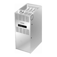
FIGURE 11
Screw
Bottom Panel
Bottom Cap
Removing the Bottom Panel
Remove the two screws that secure the bottom cap to the
furnace. Pivot the bottom cap down to release the bottom
panel. Once the bottom panel has been removed, reinstall
the bottom cap. See figure 11.
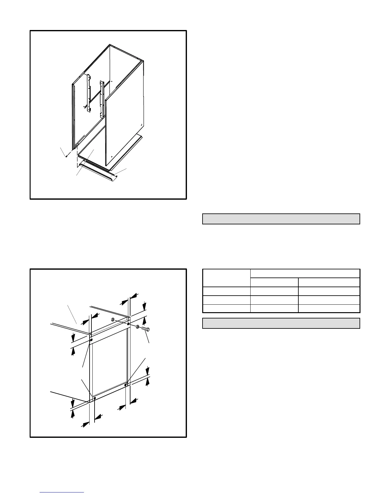
FIGURE 12
1−3/4
(44)
1−3/4
(44)
3/8
(10)
1−3/4 (44)
3/8
(10)
3/8
(10)
3/8
(10)
1−3/4
(44)
Leveling Bolt Installation
Leveling Bolt
Locations
Leveling Bolt
Locations
Inches (mm)
Furnace Front
Furnace
Bottom
Leveling an Upflow Unit
When the side return air inlets are used in an upflow ap-
plication, it may be necessary to install leveling bolts on the
bottom of the furnace. Use field−supplied corrosion−resist-
ant 5/16 inch machine bolts (4) and nuts (8). See figure 12.
NOTE − The maximum length of the bolt is 1−1/2 inches.
1 − Lay the furnace on its back and drill a 5/16 inch diame-
ter hole in each corner of the furnace’s bottom. See fig-
ure 12 for the correct location of the holes. Drill through
the bottom panel and the bottom flange of the cabinet.
2 − Install one bolt and two nuts into each hole. Screw the
first nut onto a bolt and then insert the bolt into a hole. A
flat washer may be added between the nut and the bot-
tom of the unit.
3 − Screw another nut onto the bolt on the inside of the fur-
nace base. A flat washer may be added between the
nut and the bottom of the unit.
4 − Adjust the outside nut to the appropriate height and
tighten the inside nut to secure the arrangement.
NOTE − The unit may be tilted back−to−front a maximum of
1/2". This will ensure proper draining of the heat exchang-
er.
Filters
This unit is not equipped with a filter or rack. A field−pro-
vided filter is required for the unit to operate properly. Table
1 lists recommended filter sizes.
A filter must be in place whenever the unit is operating.
TABLE 1
Furnace
Cabinet Width
Filter Size
Side Return Bottom Return
17−1/2" 16 X 25 X 1 (1) 16 X 25 X 1 (1)
21" 16 X 25 X 1 (1) 20 X 25 X 1 (1)
24−1/2" 16 X 25 X 1 (2) 24 X 25 X 1 (1)
Duct System
Use industry-approved standards to size and install the
supply and return air duct system. This will result in a quiet
and low-static system that has uniform air distribution.
NOTE − Operation of this furnace in heating mode (indoor
blower operating at selected heating speed) with an exter-
nal static pressure which exceeds 0.5 inches w.c. may re-
sult in erratic limit operation.
Supply Air Plenum
If the furnace is installed without a cooling coil, a removable
access panel should be installed in the supply air duct. The
access panel should be large enough to permit inspection
(by reflected light) of the heat exchanger for leaks after the
furnace is installed. The furnace access panel must always
be in place when the furnace is operating and it must not
allow leaks into the supply air duct system.

 Loading...