Page 28
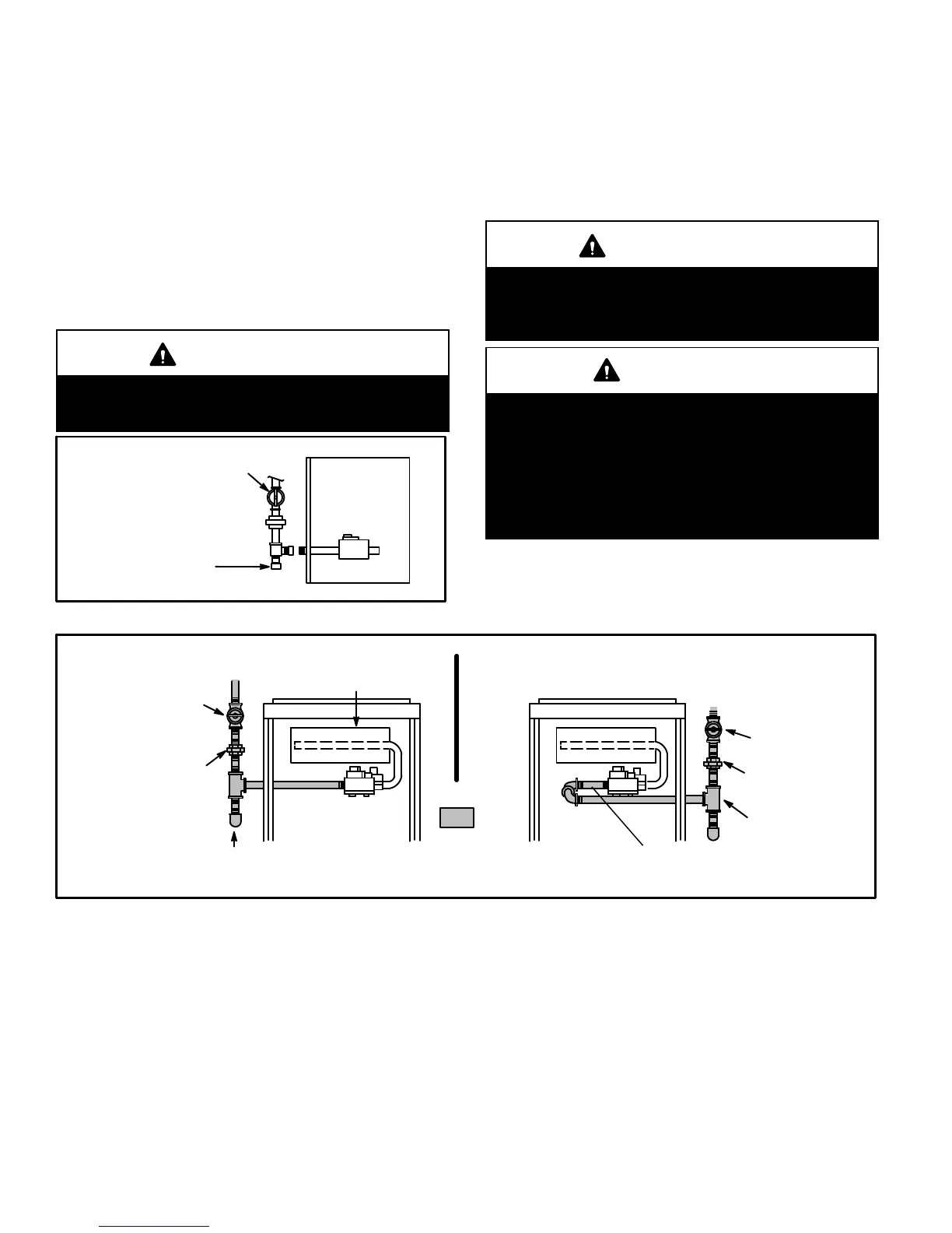
4 − Piping should be sloped 1/4 inch per 15 feet (6mm per
5.6m) upward toward the gas meter from the furnace.
The piping must be supported at proper intervals, ev-
ery 8 to 10 feet (2.44 to 3.05m), using suitable hangers
or straps. Install a drip leg in vertical pipe runs to serve as
a trap for sediment or condensate.
5 − A 1/8" N.P.T. plugged tap or pressure post is located
on the gas valve to facilitate test gauge connection.
See figures 45 and 46.
6 − In some localities, codes may require installation of a
manual main shut-off valve and union (furnished by in-
staller) external to the unit. Union must be of the
ground joint type.
IMPORTANT
Compounds used on threaded joints of gas piping
must be resistant to the actions of liquified petro-
leum gases.
FIGURE 37
MANUAL MAIN SHUT−OFF
VALVE WILL NOT HOLD
NORMAL TEST PRESSURE
CAP
FURNACE
ISOLATE
GAS VALVE
Leak Check
After gas piping is completed, carefully check all piping
connections (factory− and field−installed) for gas leaks. Use
a leak detecting solution or other preferred means.
The furnace must be isolated from the gas supply system
by closing its individual manual shut-off valve during any
pressure testing of the gas supply system at pressures less
than or equal to 1/2 psig (3.48 kPa, 14 inches w.c.).
IMPORTANT
When testing pressure of gas lines, gas valve must
be disconnected and isolated. See figure 37. Gas
valves can be damaged if subjected to pressures
greater than 1/2 psig (3.48 kPa).
WARNING
FIRE OR EXPLOSION HAZARD
Failure to follow the safety warnings exactly could
result in serious injury, death, or property damage.
Never use an open flame to test for gas leaks. Check
all connections using a commercially available soap
solution made specifically for leak detection.Some
soaps used for leak detection are corrosive to certain
metals. Carefully rinse piping thoroughly after leak
test has been completed.
GROUND
JOINT
UNION
AUTOMATIC
GAS VALVE
(with manual
shut−off valve)
FIELD
PROVIDED
AND INSTALLED
Left Side Piping
(Standard)
DRIP LEG
MANUAL
MAIN SHUT−OFF
VALVE
GROUND
JOINT
UNION
DRIP LEG
MANUAL
MAIN SHUT−OFF
VALVE
Right Side Piping
(Alternate)
In LP/propane applications using a Honeywell
VR8205 gas valve, a 4" BIP nipple must be installed
to accommodate the low inlet pressure switch.
FIGURE 38

 Loading...