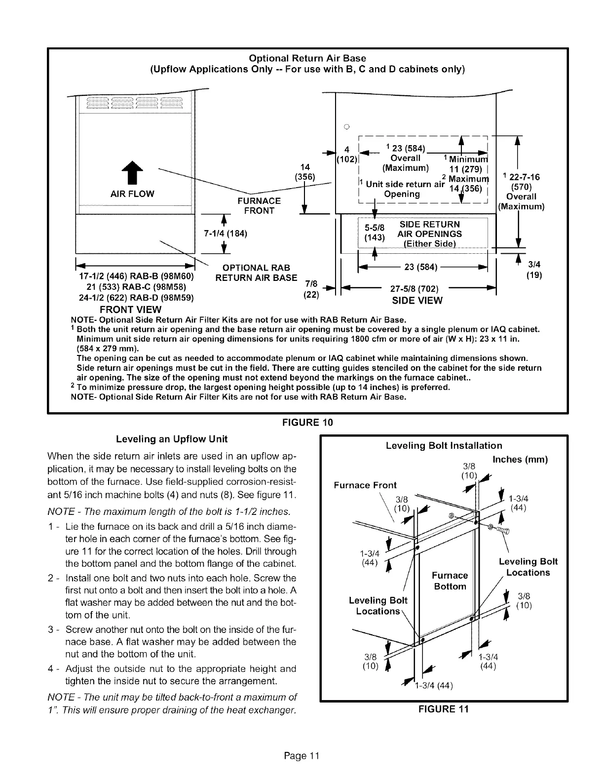
Optional Return Air Base
(Upflow Applications Only -- For use with B, C and D cabinets only)
J
AIR FLOW
14
FU%CEL
7-1/4 (184)
i _ y
17-1/2 (446) RAB-B (98M60)
21 (533) RAB-C (98M58)
24-1/2 (622) RAB-D (98M59)
FRONT VIEW
OPTIONAL RAB
RETURN AIR BASE
7/8
(22)
I
O
4 I 123 (584)
102)1_l--- Overall 1Minimu_n_
I (Maximum) 11 (279) I
2 Maximurq
I1Unit side return air
Opening 11_356)jn
5 8 SIDE RETURN
,_45_-1 AIR OPENINGS
(EitherSide).......................................................J.
ql_ 23 (584) "_u
_1-- 27-5/8 (702)
SIDE VIEW
f
1 22-7-16
(570)
Overall
Maximum)
_l
_ 3/4
(19)
NOTE- Optional Side Return Air Filter Kits are not for use with RAB Return Air Base.
1 Both the unit return air opening and the base return air opening must be covered by a single plenum or IAQ cabinet.
Minimum unit side return air opening dimensions for units requiring 1800 cfm or more of air (W x H): 23 x 11 in.
(584 x 279 mm).
The opening can be cut as needed to accommodate plenum or IAQ cabinet while maintaining dimensions shown.
Side return air openings must be cut in the field. There are cutting guides stenciled on the cabinet for the side return
air opening. The size of the opening must not extend beyond the markings on the furnace cabinet..
2 To minimize pressure drop, the largest opening height possible (up to 14 inches) is preferred.
NOTE- Optional Side Return Air Filter Kits are not for use with RAB Return Air Base.
FIGURE 10
Leveling an Upflow Unit
When the side return air inlets are used in an upflow ap-
plication, it may be necessary to install leveling bolts on the
bottom of the furnace. Use field-supplied corrosion-resist-
ant 5/16 inch machine bolts (4) and nuts (8). See figure 11.
NOTE - The maximum length of the bolt is 1-1/2 inches.
1 - Lie the furnace on its back and drill a 5/16 inch diame-
ter hole in each corner of the furnace's bottom. See fig-
ure 11 for the correct location of the holes. Drill through
the bottom panel and the bottom flange of the cabinet.
2 - Install one bolt and two nuts into each hole. Screw the
first nut onto a bolt and then insert the bolt into a hole. A
flat washer may be added between the nut and the bot-
tom of the unit.
3 - Screw another nut onto the bolt on the inside of the fur-
nace base. A flat washer may be added between the
nut and the bottom of the unit.
4 - Adjust the outside nut to the appropriate height and
tighten the inside nut to secure the arrangement.
NOTE - The unit may be tilted back-to-front a maximum of
1". This willensure proper draining of the heat exchanger.
Leveling Bolt Installation
Inches (mm)
3/8
(1o)
Furnace Front
3/8 1-3/4
(44)
1-3/4
(44)
Leveling Bolt
Leveling Bolt
Locations
3/8
(1o)
3/8 1-3/4
(10) (44)
t-3/4 (44)
FIGURE 11
Page 11
 Loading...


