Downflow Applications
The unit may be installed three ways in downfiow applica-
tions: on non-combustible flooring, on combustible flooring
using an additive base, or on a reverse-flow cooling cabi-
net. Do not drag the unit across the floor in the down-
flow position. Flange damage will result.
After unit has been properly set in place, position provided
logo over existing logo and affix sticker on front panel.
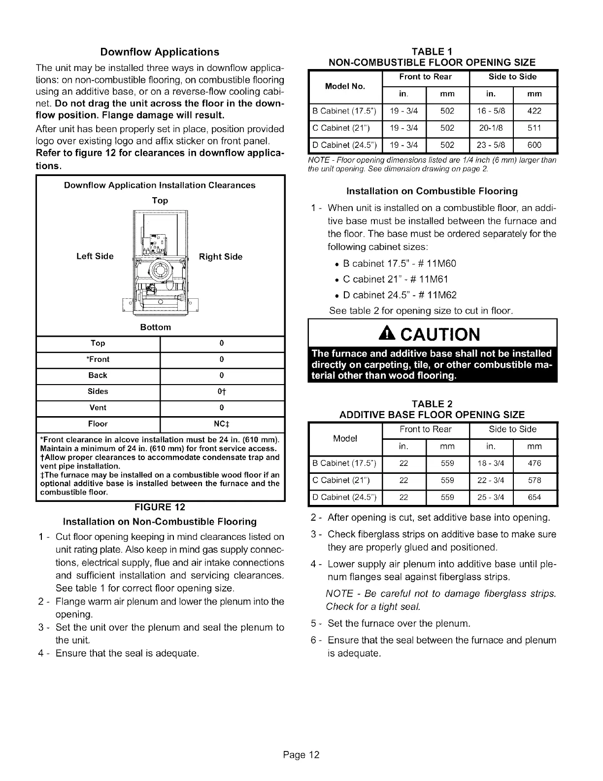
Refer to figure 12 for clearances in downflow applica-
tions.
Downflow Application Installation Clearances
Top
Left Side
Right Side
Bottom
Top 0
*Front 0
Back 0
Sides 0t
Vent 0
Floor NC$
*Front clearance in alcove installation must be 24 in. (610 ram).
Maintain a minimum of 24 in. (610 ram) for front service access.
tAllow proper clearances to accommodate condensate trap and
vent pipe installation.
SThe furnace may be installed on a combustible wood floor if an
optional additive base is installed between the furnace and the
combustible floor.
FIGURE 12
Installation on Non-Combustible Flooring
1 - Cut floor opening keeping in mind clearances listed on
unit rating plate. Also keep in mind gas supply connec-
tions, electrical supply, flue and air intake connections
and sufficient installation and servicing clearances.
See table 1 for correct floor opening size.
2 - Flange warm air plenum and lower the plenum into the
opening.
3 - Set the unit over the plenum and seal the plenum to
the unit.
4 - Ensure that the seal is adequate.
TABLE 1
NON-COMBUSTIBLE FLOOR OPENING SIZE
Model No.
B Cabinet (17.5")
C Cabinet (21")
D Cabinet (24.5")
NOTE - Floor openin
Front to Rear
in. mm
19 - 3/4 502
19 - 3/4 502
19 - 3/4 502
Side to Side
in.
16 - 5/8
20-1/8
23 - 5/8
mm
422
511
6OO
dimensions listed are 1/4 inch (6 mm) larger than
the unit opening. See dimension drawing on page 2.
Installation on Combustible Flooring
1 - When unit is installed on a combustible floor, an addi-
tive base must be installed between the furnace and
the floor. The base must be ordered separately for the
following cabinet sizes:
• B cabinet 17,5"-# 11M60
• C cabinet 21"- # 11M61
• D cabinet 24,5" - # 11M62
See table 2 for opening size to cut in floor,
A, CAUTION
TABLE 2
ADDITIVE BASE FLOOR OPENING SIZE
Model
B Cabinet (17.5")
C Cabinet (21")
D Cabinet (24.5")
2-
3-
Frontto Rear
in. mm
22 559
22 559
22 559
Side to Side
in.
18 - 3/4
22 - 3/4
25 - 3/4
mm
476
578
654
After opening is cut, set additive base into opening.
Check fiberglass strips on additive base to make sure
they are properly glued and positioned,
4 - Lower supply air plenum into additive base until ple-
num flanges seal against fiberglass strips.
NOTE - Be careful not to damage fiberglass strips.
Check for a tight seaL
5 - Set the furnace over the plenum,
6 - Ensure that the seal between the furnace and plenum
is adequate,
Page 12
 Loading...


