G61MPV UNIT
SUPPLY AIR PLENUM
PROPERLY
SIZED FLOOR _X_,J_€ "
OPENING I\\_ L_ ADDITIVE BASE
FIGURE 13
Installation on Cooling Cabinet
1 - Refer to reverse-flow coil installation instructions for
correctly sized opening in floor and installation of cabi-
net,
2 - When cooling cabinet is in place, set and secure the
furnace according to the instructions that are provided
with the cooling coil, Secure the furnace to the cabinet,
3 - Seal the cabinet and check for air leaks,
Return Air Opening -- Downflow Units
Return air may be brought in only through the top opening
of a furnace installed in the downflow position.The follow-
ing steps should be taken when installing plenum:
1 - Bottom edge of plenum should be flanged with a
hemmed edge (See figure 14 or 15),
2 - Sealing strips should be used to ensure an airtight seal
between the cabinet and the plenum.
3 - In all cases, plenum should be secured to top of fur-
nace using sheet metal screws,
4 - Make certain that an adequate seal is made,
PLENUM ----__ I""11"_
(Field Provided) _ SECURE FROM
• _UTSIDE CABINET
/ v II .. CABINET
SEALING STRIP _ IIJ SIDE PANEL
(Field Provided) ...... II
Side View II
FIGURE 14
PLENUM _
(Field Provided)
SECURE FROM
INSIDE CABINET
Side View
SEALING STRIP
Field Provided)
CABINET
SIDE PANEL
FIGURE 15
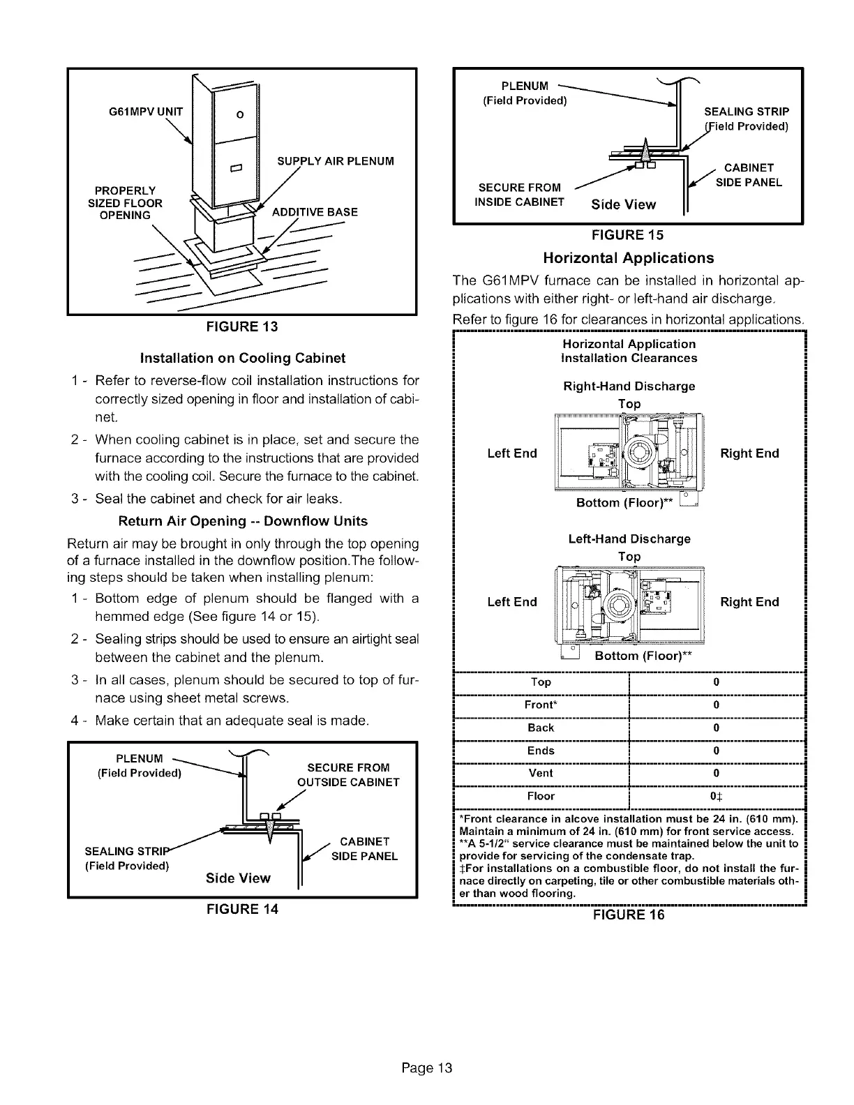
Horizontal Applications
The G61MPV furnace can be installed in horizontal ap-
plications with either right- or left-hand air discharge,
Refer to figure 16 for clearances in horizontal applications,
================================================================================================
Horizontal Application
Installation Clearances
Right-Hand Discharge
Top
Left End Right End
Left-Hand Discharge
Top
Left End Right End
Bottom (Floor)**
i........................................i.............................................]
Front* i O
'.................... ....................t..............................................
I
Ends ! O
Floor i O:_
*Front clearance in alcove installation must be 24 in. (610 ram).
Maintain a minimum of 24 in. (610 ram) for front service access.
**A 5-I12" service clearance must be maintained below the unit to
provide for servicing of the condensate trap.
i :]:For installations on a combustible floor, do not install the fur-
l nace directly on carpeting, tile or other combustible materials oth-
Ler.t.h.an. w.°° d.f.I.°.°ri.n,g: ...............................................................
FIGURE 16
Page 13
 Loading...


