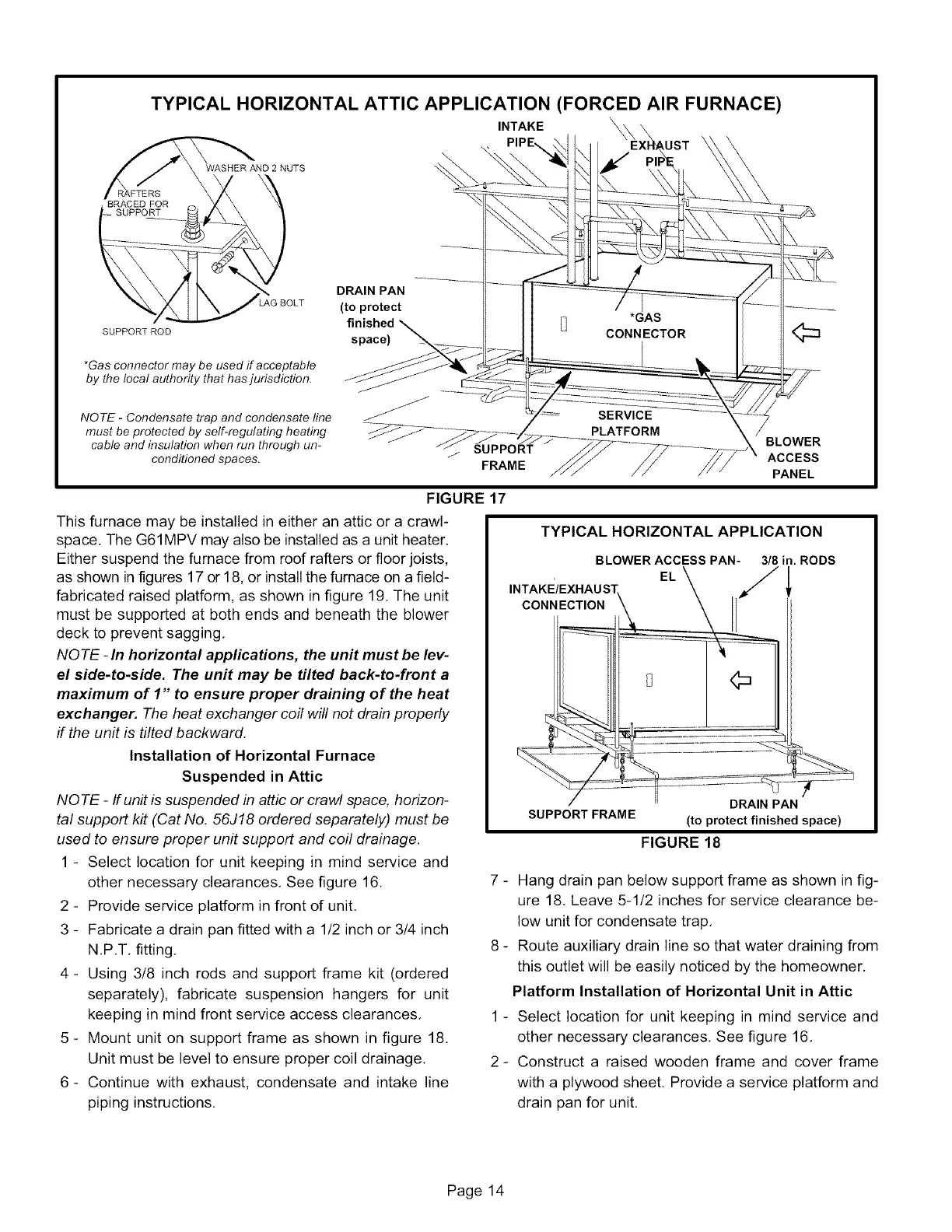
TYPICAL HORIZONTAL ATTIC APPLICATION (FORCED AIR FURNACE)
INTAKE \
SAFTERS
BRACED FOR
SUPPORT
WASHER AND 2 NUTS
\
LAG BOLT
SUPPORT ROD
*Gas connector may be used if acceptable
by the local authority that has jurisdiction.
NOTE - Condensate trap and condensate line
must be protected by self-regulating heating
cable and insulation when run through un-
conditioned spaces.
DRAIN PAN
(to protect
finished
space)
j SUPPORT
FRAME
FIGURE 17
This furnace may be installed in either an attic or a crawl-
space. The G61MPV may also be installed as a unit heater.
Either suspend the furnace from roof rafters or floor joists,
as shown in figures 17 or 18, or install the furnace on a field-
fabricated raised platform, as shown in figure 19. The unit
must be supported at both ends and beneath the blower
deck to prevent sagging,
NQ TE - In horizontal applications, the unit must be lev-
el side-to-side. The unit may be tilted back-to-front a
maximum of 1" to ensure proper draining of the heat
exchanger. The heat exchanger coil will not drain properly
if the unit is tilted backward.
Installation of Horizontal Furnace
Suspended in Attic
NQ TE - If unit is suspended in attic or crawl space, horizon-
tal support kit (Cat No. 56J18 ordered separately) must be
used to ensure proper unit support and coil drainage,
1 - Select location for unit keeping in mind service and
other necessary clearances. See figure 16. 7 -
2 - Provide service platform in front of unit.
3 - Fabricate a drain pan fitted with a 1/2 inch or 3/4 inch
N.P.T. fitting. 8 -
4- Using 3/8 inch rods and support frame kit (ordered
separately), fabricate suspension hangers for unit
keeping in mind front service access clearances. 1 -
5 - Mount unit on support frame as shown in figure 18.
Unit must be level to ensure proper coil drainage. 2 -
6- Continue with exhaust, condensate and intake line
piping instructions.
BLOWER
ACCESS
PANEL
TYPICAL HORIZONTAL APPLICATION
BLOWER ACCESS PAN- 318in, RODS
INTAKE/ExHAUST EL
CONNECTION _
DRA,N
SUPPORT FRAME (to protect finished space)
FIGURE 18
Hang drain pan below support frame as shown in fig-
ure 18. Leave 5-1/2 inches for service clearance be-
low unit for condensate trap,
Route auxiliary drain line so that water draining from
this outlet will be easily noticed by the homeowner,
Platform Installation of Horizontal Unit in Attic
Select location for unit keeping in mind service and
other necessary clearances. See figure 16,
Construct a raised wooden frame and cover frame
with a plywood sheet, Provide a service platform and
drain pan for unit,
Page 14
 Loading...


