Page 38
FIGURE 36
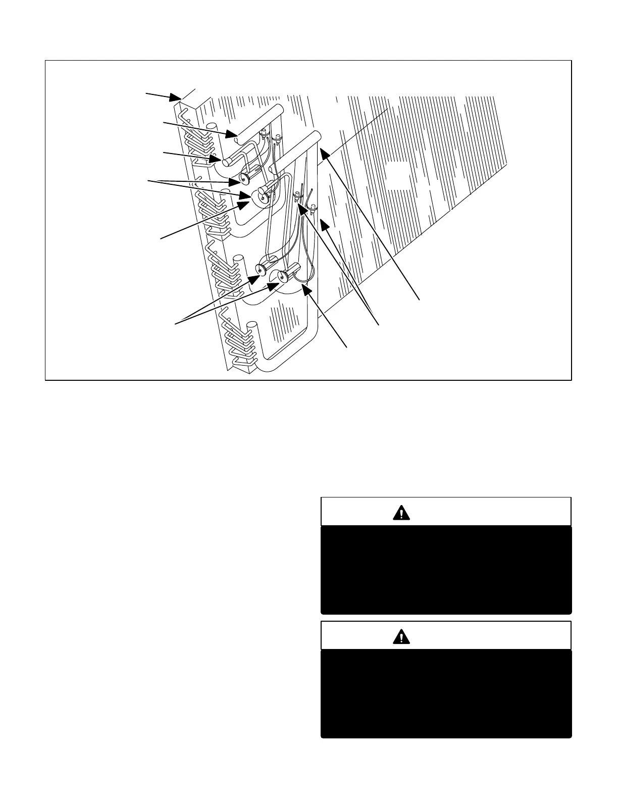
GCS162553, 2753, 3003 PLUMBING COMPONENTS
EVAPORATOR SECTION
2
1
1st STAGE SUCTION
RETURN TO COMPRESSOR
1st STAGE
COMP. 1
EVAPORATOR COIL
2nd STAGE
COMP. 2
EVAPORATOR COIL
DUAL 1st STAGE
EXPANSION VALVES
DUAL 2nd STAGE
EXPANSION VALVES
2nd STAGE LIQUID
LINE FROM OUTDOOR COIL
1st STAGE LIQUID
LINE FROM OUTDOOR COIL
SENSING BULBS
EQUALIZER LINES
2nd STAGE SUCTION
RETURN TO COMPRESSOR
1-Compressors B1, B2 and B13
Compressors are supplied by various manufacturers. All units
are equipped with two independent cooling circuits except 15
ton units which are equipped with three independent cooling
circuits. Compressor electrical specifications vary by
manufacturer. Likewise, compressor capacity may vary from
first stage to second stage. In all cases, the capacity of each
compressor is added to reach the total capacity of the unit.
See unit rating plate for specific compressor capacity ratings
and electrical data.
Units with two cooling circuits:
Compressor B1 is compressor 1. It operates during all
cooling demand and is energized by contactor K1 upon re
ceiving a first stage demand. Compressor B2 is compres
sor 2. It operates only during second stage cooling de
mand and is energized by contactor K2 upon receiving a
second stage demand.
NOTE-Refer to wiring diagram section B9 for specific
unit operation.
Units with three cooling circuits:
Compressor B1 is compressor 1. It operates during all cool
ing demand and is energized by contactor K1 upon receiv
ing a first stage demand. Compressor B2 is compressor 2.
It operates only during first stage cooling demand and is en
ergized by contactor K2 upon receiving a first stage de
mand (after time delay DL15 closes). Compressor B13 is
compressor 3. It is energized by contactor K14 upon receiv
ing a second stage demand.
Each compressor used in GCS16 units is equipped with a
selfregulating crankcase heater. All compressors are pro
tected by internal overload protection circuitry.
WARNING
Electrical shock hazard. Compressor must be
grounded. Do not operate without protective cov
er over terminals. Disconnect power before re
moving protective cover. Discharge capacitors
before servicing unit. Failure to follow these pre
cautions could cause electrical shock resulting in
injury or death.
WARNING
Crankcase heaters must be energized for 24
hours before attempting to start compressors.
Set thermostat so there is no compressor demand
before closing disconnect switch. Attempting to
start compressors during the 24hour warmup
period could result in damaged or failed compres
sors.
 Loading...
