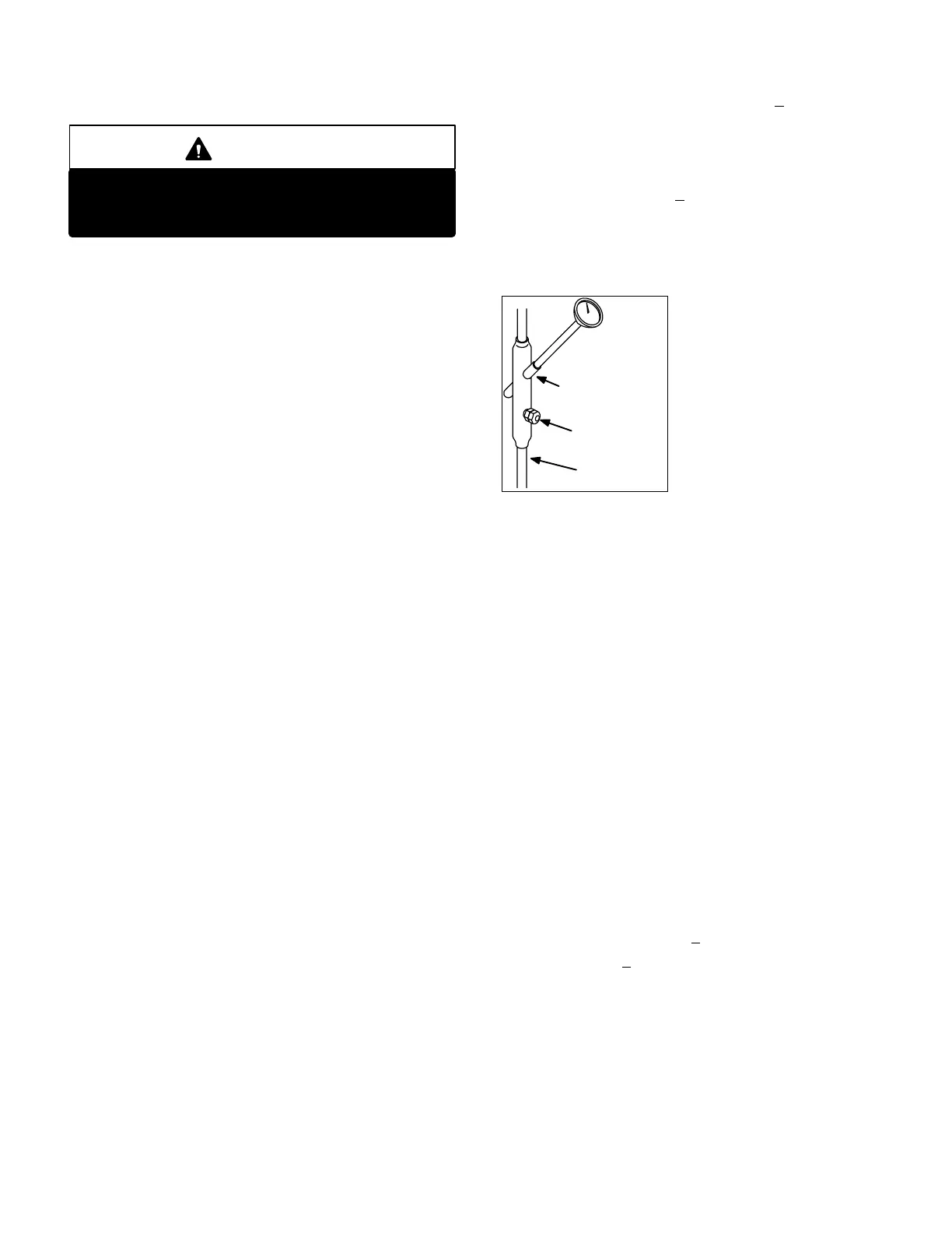
FIGURE 37
THERMOMETER
WELL
LIQUID LINE
GAUGE PORT
LIQUID LINE
Page 39
2-Crankcase Heaters HR1, HR2 and HR5
CAUTION
Selfregulating crankcase heaters are connected
to line voltage at all times (not switched by unit
circuitry.)
All compressors are equipped with self- regulating type
crankcase heaters. Fifteen ton and smaller units use inser
tion type heaters while 18.5 ton and larger units use belly
band style heaters. Heater HR1 is installed in compressor
B1, heater HR2 is installed in compressor B2 and heater
HR5 is installed in compressor B13 (if unit is equipped with
three compressors). Crankcase heater wattage varies by
compressor manufacturer. See unit rating plate for specific
electrical data.
3-High Pressure Limit S4, S7 and S28
The high pressure limit is a manually reset SPST N.C.
switch which opens on a pressure rise. All GCS16 units
are equipped with this limit. The switch is located in the
compressor discharge line and is wired in series with the
compressor contactor.
In three pump systems, S4 is wired in series with the first
stage compressor 1 contactor, S7 is wired in series with
the first stage compressor 2 contactor and S28 is wired in
series with the second stage compressor 3 contactor. In
two pump systems, S4 is wired in series with the first stage
compressor contactor and S7 is wired in series with the
second stage compressor contactor.
When discharge pressure rises above 410+10 psig (indi
cating a problem in the system) the switch opens and the
respective compressor is de-energized (the economizer
can continue to operate.) After the problem has been
found and corrected, the switch can be reset by pushingin
the switch button.
4-Loss of Charge Switch S24, S25 and S34
The loss of charge switch is an autoreset SPST N.C.
switch which opens on a pressure drop (almost complete
loss of charge). All GCS16 units are equipped with this
switch. The switch is located in the compressor discharge
line next to the high pressure switch and is wired in series
with the high pressure switch and compressor contactor.
In three pump systems, S24 is wired in series with first
stage (compressor #1) contactor K1, S25 is wired in series
with first stage (compressor #2) contactor K2 and S34 is
wired in series with the second stage (compressor #3)
contactor K14. In two pump systems, S24 is wired in series
with first stage compressor contactor and S25 is wired in
series with second stage compressor contactor.
When discharge pressure drops below 25+5 psig (indicat
ing a loss of charge in the system) the switch opens and
the compressor is de-energized. The switch automatically
resets when refrigerant is added and pressure in the dis
charge line rises above 55+5 psig.
5-Thermometer Well (Figure 37)
All units are factory
equipped with a thermome
ter well for charging the unit.
The well is used to accurate
ly measure the temperature
of the liquid line. The tem
perature measured is then
used to calculate the ap
proach or subcooling tem
perature. Approach and
subcooling temperatures
are compared to tables
printed in the charging section of this manual to determine
the correct charge. Thermometer wells are equipped with
a gauge port for high pressure gauge connection.
To accurately measure the temperature of the liquid line,
the well should be filled with a light mineral oil before using.
This will ensure good heat transfer to the thermometer.
6-Freezestats S49, S50 and S53
Each evaporator is equipped with a low temperature limit
located on a suction feeder. In three pump systems, S49 is
located on the first stage compressor 1 coil, S50 is located
on the first stage compressor 2 coil and S53 is located on
the second stage coil. In two pump systems, S49 is lo
cated on the first stage evaporator coil and S50 is located
on the second stage evaporator coil.
Each freezestat is wired in series with its respective com
pressor contactor coil. Each freezestat is a SPST auto-re
set limit which opens at 29°F + 3°F on a temperature drop
and closes at 58°F + 4°F on a temperature rise. To prevent
coil icing, the freezestats open during compressor opera
tion to temporarily disable the respective compressor until
the coil warms sufficiently to melt any accumulated frost.
If the freezestats are tripping frequently due to coil icing,
check the unit charge, airflow and filters before allowing unit
back in operation. Make sure to eliminate all conditions
which might promote evaporator ice buildup.
 Loading...
