Page 27
System Operation
This section describes how to operate the Harmony
®
II con-
trol panel and how the system reacts to each operation.
A−Zone Thermostats
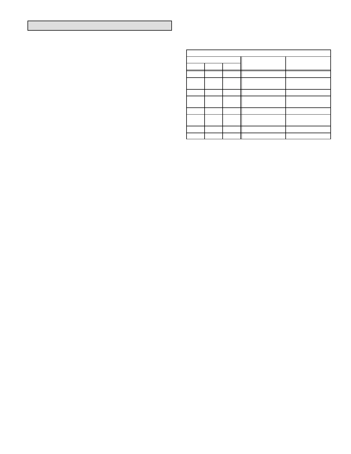
Table 2 shows how the Harmony
®
II control center inter-
prets zone thermostat inputs. The control center distin-
guishes between heat pump and heat/cool thermostats by
looking at how the INDOOR UNIT jumper is set on the con-
trol center.
Cool / Heat / Auto−Changeover Modes
Zone thermostats send a heating or cooling signal to
the Harmony
®
II control center.
The thermostat servicing zone 1 is called the master
thermostat. Remaining thermostats are called zone 2
thermostat, zone 3 thermostat, and zone 4 thermostat.
Conventional thermostats with switching subbases are
used with the Harmony
®
II control system. The thermostats
may be standard or auto-changeover type. It does not mat-
ter how the thermostats are set; they should be simply set
for the level of comfort desired.
Gas heating (G32V/G21V/GSR21V) systems: Standard
heat/cool thermostats are used.
Heat pump systems: Heat pump heat/cool thermostats are
used.
For example, one thermostat may be set for cooling and
the others set for heating. If auto-changeover thermostats
are used, any or all of the thermostats may be set for auto-
changeover. The best efficiency will be maintained if all
zone thermostats are set with the setpoint close to one
another. This will minimize the number of changeovers the
system will have to initiate in order to satisfy an opposing de-
mand.
Fan On / Auto Mode
Zone thermostat indoor blower control is disconnected
and performs no function.
Indoor blower On / Auto selection is made at the Harmony
®
II control panel.
The service light in the master thermostat is connected
to the outdoor unit. The light is turned on when the
compressor in the outdoor unit needs servicing. The
service light in the remaining zone thermostats is dis-
connected.
Service Light (Heat pump only)
Emergency Heat (Heat pump only)
The emergency heat switch in any thermostat does not
allow the compressor in the outdoor unit to operate in
response to a thermostat heating demand. The indoor
unit supplies all of the heat. The emergency heat light
is turned on when the switch is engaged, and the auxil-
iary source is used to satisfy the heating demand in that
zone. The emergency heat switch in the remaining
zone thermostats provides similar a function.
When the emergency heat switch is turned on (any
zone thermostat), the auxiliary source is used to satis-
fy heating demand in that zone.
Table 2
Harmony
®
II Thermostat Input Interpretation
Thermostat Output
G32V/G21V CB31MV Heat
O W Y
Gas Heat Systems
Pump System
Off Off Off No Demand No Demand
Off Off On Cooling Demand
Compressor
Heating Demand
Off On Off Heating Demand Em. Heat
Off On On Error Code #10
Compressor and
Auxiliary Heat
On Off Off Error Code #10 No Demand
On Off On Error Code #10
Cooling Cooling
Demand
On On Off Error Code #10 Error Code #10
On On On Error Code #10 Error Code #10
B−Harmony
®
II Control Panel Cool / Heat /
Auto−Changeover Modes
Cool, heat, or auto selection on the control panel deter-
mines what type of thermostat demand will be satisfied.
Heating Mode
When the user selects the Heat mode at the control
panel, the zone control system will only respond to
heating demands from the zone thermostat(s).
Heat modulation and regulation is coordinated between
the Harmony
®
II control panel and the indoor unit (furnace
or blower coil). When heating demands are satisfied, air is
delivered to the last demanding zone until the furnace has
cooled. If the system is operating in Fan-On mode and
heating demands have been satisfied, air is delivered to
the last demanding zone until the furnace has cooled. All
dampers then open and air circulates to all zones.
Cooling Mode
When the user selects the Cool mode at the control
panel, zone control system will only respond to cooling
demands from the zone thermostat(s).
When the system is in Cooling, the system responds to
cooling demands from any zone thermostat. The only
dampers to remain open are those supplying air to the de-
manding zone(s); all other dampers will close. The blower
operates at a speed determined by the position of the CFM
selection jumpers located on the control center.
On two−speed condensing units, selection between high
speed or low speed is determined by the discharge air tem-
perature. The normal speed change delay (located inside
the two-speed unit) applies. On two-speed and single−
speed applications, if the discharge air temperature cross-
es a minimum operating temperature, the compressor
cycles off (to protect from freeze-up). The compressor is
protected against short cycling by a five−minute time delay.
 Loading...