Page 7
System Components
Harmony
®
II Control Components
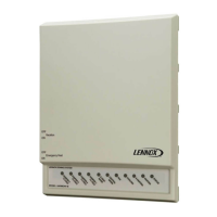
Control Panel (Figure 1)The user selects the mode of
operation on the Harmony
®
II control panel. Raised but-
tons and corresponding LEDs for each mode are on the
control panel.
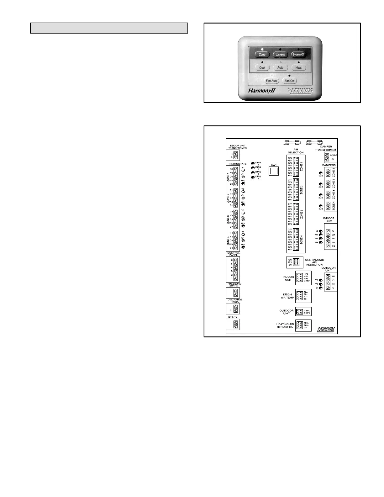
Control Center (Figure 2)The control center is the brain"
of the zone control system. The control organizes the opera-
tion of the thermostats, dampers, and HVAC equipment for to-
tal comfort.
Other System Components (Ordered Separately)
ThermostatsThermostats are required for each zone and
may be programmable or conventional but must have a dead
band between HEAT and COOL. In Central Control mode, the
zone 1 thermostat is designated as the master thermostat.
The other thermostats are not used. In the Zone Control
mode, the unused zones are referred to as zone 2, zone 3,
and zone 4.
Dampers and Damper TransformerMotorized damp-
ers are used in the supply duct system to allow air distribu-
tion to the zones. The dampers use 24VAC to close and
spring−return to open.
The dampers are powered by a separate, field−provided
24VAC transformer. The transformer must have an ade-
quate VA rating for the number of operating dampers.
Discharge Air Temperature ProbeA discharge air tem-
perature probe or sensor monitors the supply air. This
probe gathers temperature information across the air
stream. It is not a limit switch.
Pressure SwitchA pressure switch is required for ap-
plications with a Lennox heat pump (Options 2 and 3). The
pressure switch acts as a safety device in case of high
head pressures during first− and second−stage heating.
Temperature Modulation SwitchWhen applying the
Harmony
®
II zone control system to the G32V furnace (op-
tions 1 and 3), you must install a temperature modulation
switch. The switch senses the temperature of the supply
air. Based on that air temperature, the switch will allow the
gas valve to change from high fire to low fire or from low fire
to high fire. The normally closed switch (72 H45) is not sup-
plied with the zoning control or with the furnace and must
be ordered separately.
Harmony
®
II Control Panel
Figure 1
Harmony
®
II Control Center
or Gas
−
or Gas
Discharge/
Bypass But-
ton
Figure 2
 Loading...