Page 18
Outdoor Unit Jumper
Position the outdoor unit jumper
according to the speed of the out-
door unit. For single−speed units,
place jumper on 1 SPD; for two−
speed units, place jumper on 2
SPD. See figure 15.
Discharge Air Temperature Jumper
The discharge air temperature jumper enables the dis-
charge air setpoints to be adjusted. The discharge ther-
mostat probe in the supply plenum sends a signal with
temperature information to the Harmony
®
II control
board. These jumper settings are only activated in ap-
plications that use either a two−speed condensing unit
or a two−speed heat pump. The H+ or H− setting will ad-
just the discharge temperature setpoint in applications
with two−speed heat pump or with single−speed heat
pumps with staged auxiliary heat. Therefore, the heat-
ing discharge temperature setpoint cannot be adjusted
for Option 1. The C+ or C− selection adjusts the cooling
setpoint in applications with a two−speed outdoor unit
only.
One heating and one cooling
adjustment may be made. This
jumper allows adjustment (by
5F) to the specific temperature
setpoints (see figure 16).
Jumpers may be set as follows:
H+ Raises heating temperature setpoint by 5F
H− Lowers heating temperature setpoint by 5F
C+ Raises cooling temperature setpoint by 5F
C− Lowers cooling temperature setpoint by 5F
Common System Component Wiring
The following section shows the wiring for components
used with the zone control system and any of the three
heating and cooling equipment options. This manual cov-
ers wiring for option specific components in their respec-
tive sections.
IMPORTANT
Avoid running any control wiring close to AC house
wiring. If this cannot be avoided, limit close parallel
of power and control wiring to a few feet.
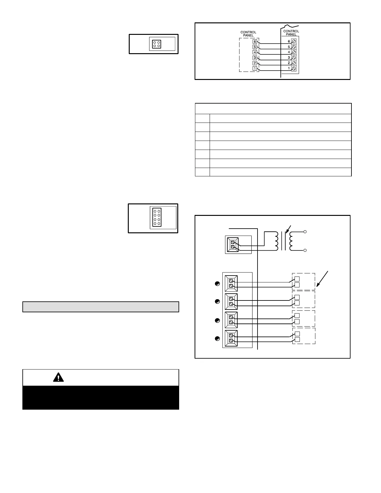
Control Panel Wiring
Connect the marked wires from the control panel to the
control center as shown in figure 17 (refer also to table 1).
Figure 17
Control
Center
Table 1
Control Panel Inputs to Control Center
Pin Description
1 Data pertaining to Central, Zone or Off mode
2 Data pertaining to Auto, Cool or Heat mode
3 Output signal to turn red service led on control panel on
4 Common
5 24VAC
6 Data pertaining to fan in Auto or On mode
Dampers & Damper Transformer Wiring
The number of dampers used will depend on the duct sys-
tem design. Use thermostat wire to connect dampers to the
control center. Connect wires as shown in figure 18.
DAMPERS
FROM EACH ZONE
(Four zone application shown)
ZONE 1
ZONE 2
ZONE 3
ZONE 4
DAMPERS
1DZ
2DZ
3DZ
4DZ
ZONE 1ZONE 2ZONE 3ZONE 4
DAMPER DAMPER DAMPER DAMPER
Figure 18
24 VAC
IN
120 VAC
DAMPER TRANSFORMER
A total of five dampers may be connected at the damper out-
put terminals on the control center. If additional dampers are
used, additional transformers and relays will be needed.
Fuse F2 will protect the damper outputs from a short circuit or
overload in the damper wiring.
If dampers are applied to the return duct system, the damp-
ers for each zone must be wired in parallel.
Use thermostat wire to connect the damper transformer to
control center terminal block as shown in figure 18. Refer to
the wiring diagram for wiring connections (figure 19).
Figure 15
1 SPD
2 SPD
OUTDOOR
UNIT
FIGURE 16
C-
DISCH
C+
H-
H+
AIR TEMP
 Loading...