GAS FURNACE
Page 29
HARMONY IIIT ZONE CONTROL SYSTEM
VSM Furnaces IFC Electrical Adjustments (G61MPV & G60UHV [cont’d])
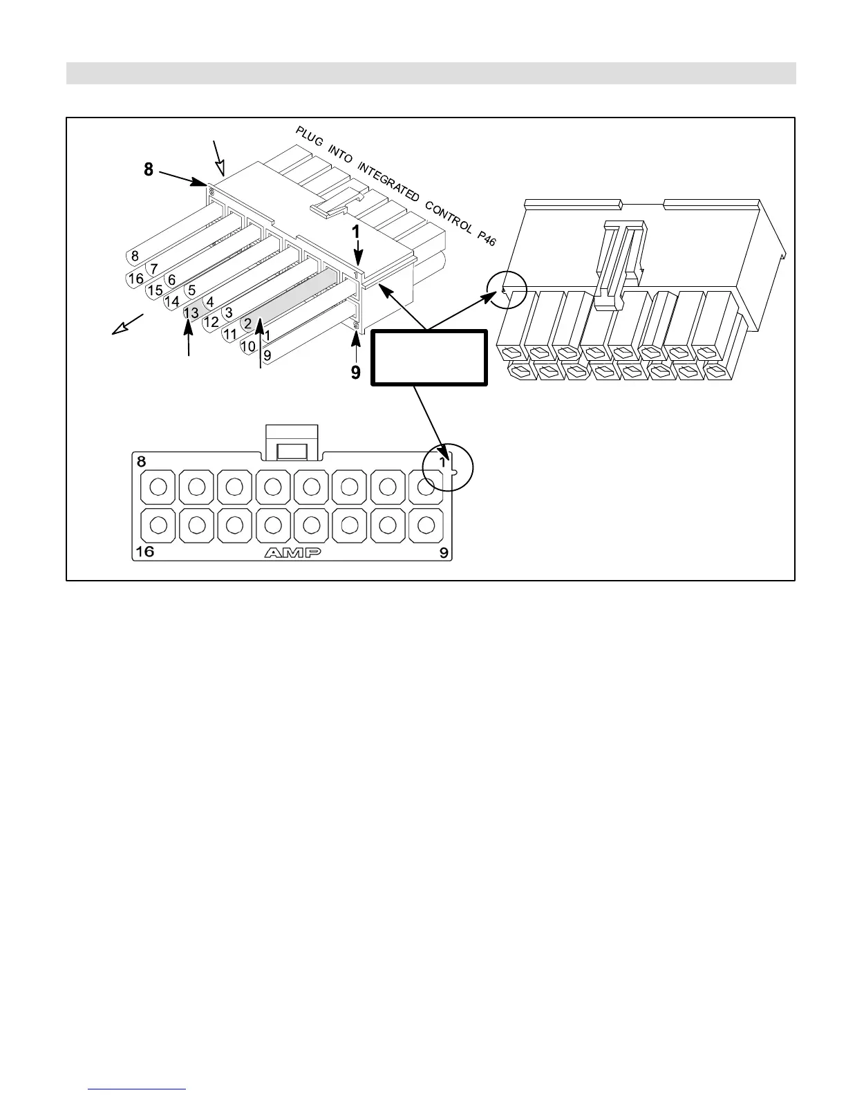
CUT AND TAPE
WIRE #13 (FURNACE
APPLICATION ONLY)
LOOK FOR RIDGE
TO IDENTIFY PIN 1
POSITION
CUT & TAPE
WIRE #2
1
9
VIEW FROM MATING SIDE OF PLUG
VIEW LOOKING DIRECTLY INTO WIRE ENTRY SIDE OF PLUG
VIEW FROM WIRE ENTRY SIDE OF PLUG
8
16
TO MOTOR J/P49
J46 PLUG FROM THE MOTOR
Figure 21. Integrated Control Cable Modifications for G61MPV/G60UHV Furnaces
Set the upper limit of blower CFM as follows:
1. Determine the maximum system CFM requirements (sum of all the individual zones).
2. From the Blower Motor Performance table (see unit installation instructions) determine the HIGH Speed cool DIP switch
setting that corresponds to this CFM.
3. Set the HIGH Speed cool DIP switch setting on the control to this value.
NOTE − The lower limit of blower CFM is factory set. It is not field adjustable. See table 6 on page 14 for minimum airflow
values for specific furnace models.
 Loading...