Page 8
I−High Pressure Switch (S4)
IMPORTANT
Pressure switch settings for R410A refrigerant will
be significantly higher than units with R22.
An auto-reset, single-pole/single-throw high pressure switch
is located in the liquid line. This switch shuts off the compres-
sor when liquid line pressure rises above the factory setting.
The switch is normally closed and is permanently adjusted to
trip (open) at 640 +
10 psi and close at 448 + 10 psi. See fig-
ure 13 for switch location.
J−Low Ambient Thermostat (S23)
(Second−Stage)
Second−stage low ambient thermostat S23 (figure 8) is a
SPST thermostat located in the compressor compartment.
The control uses a cap-tube sensor to monitor the tempera-
ture inside the compressor compartment. The cap-tube
sensor is coiled adjacent to the control.
Low Ambient Thermostat S23
Temperature Sensor
(Cap-Tube)
FIGURE 8
S23 continually monitors the temperature inside the com-
pressor compartment. When compressor compartment
temperature drops below the control setpoint, the control
closes. When the control closes, the contacts shunt across
Y1 and Y2 inside the unit. When Y1 heating demand is
present and S23 is closed, the compressor will run in high
capacity. The compressor will operate in high capacity
mode anytime there is a Y1 heating call from indoor ther-
mostat, until the units control box warms and S23 opens.
S23 has field adjustable setpoints. Temperature differential
(difference between cut-in and cut-out) is fixed and cannot
be adjusted. Table 2 shows S23 control setpoints. The con-
trol is factory set to close at 40+
2°F on a temperature drop
and reset at 50+
2°F on a temperature rise.
TABLE 2
Control Setpoints
Low Ambient Thermostat
Adjustable Range
Factory
Setting
Min. Max.
Cut-In
(Close on Temperature Drop)
40+2°F 37+2°F 55+2°F
Cut-Out
(Open on Temperature Rise)
50+2°F 47+2°F 65+2°F
Regional climatic conditions may require the control to be ad-
justed to a different setting. The adjustment screw is located
on the control. A hole cut into the bottom shelf of the control
box provides access to the control from the compressor
compartment. See figure 9.
Adjusting Low Ambient Thermostat
Adjustment screw can be
reached by inserting a screw-
driver through the slot in control
box.
Turn screw clockwise to increase
switchover temperature.
FIGURE 9
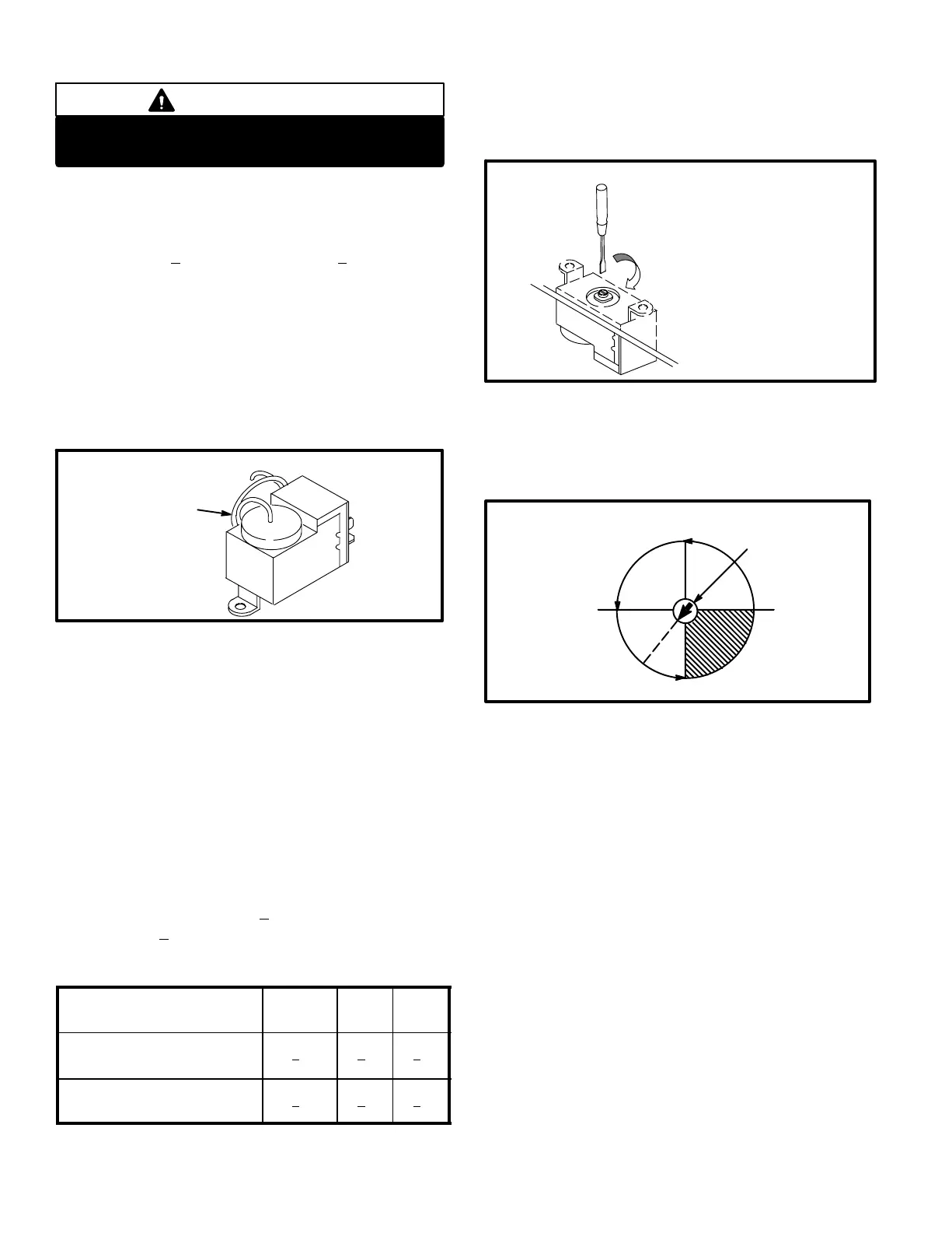
Figure 10 shows the adjustment range of the control. Turn
adjustment screw clockwise to raise the switchover tem-
perature and counterclockwise to lower the switchover
temperature.
Low Ambient Thermostat
adjustment
screw
*40
37
55
49
43
FIGURE 10
K−Reversing Valve (L1)
A refrigerant reversing valve with an electromechanical so-
lenoid is used to reverse refrigerant flow during unit opera-
tion. The reversing valve is energized during cooling de-
mand and during defrost.
L−Transformer (T46)
Transformer T46 is located in the control box and is ener-
gized any time the compressor is operating.
M−Solenoid Relay (K195)
Relay K195 is N.O. SPDT relay located in the control box.
On a Y2 call K195−1 closes allowing AC voltage from
(T46) to the two pin full wave rectifier plug (D4).
N−Rectifier Plug (D4)
D4 is a molded assembly that plugs into the compressor.
On a Y2 call D4 converts 24 volts AC to 24 volts DC. The
DC voltage energizes solenoid L34, allowing the com-
pressor to operate at full capacity.

 Loading...