13
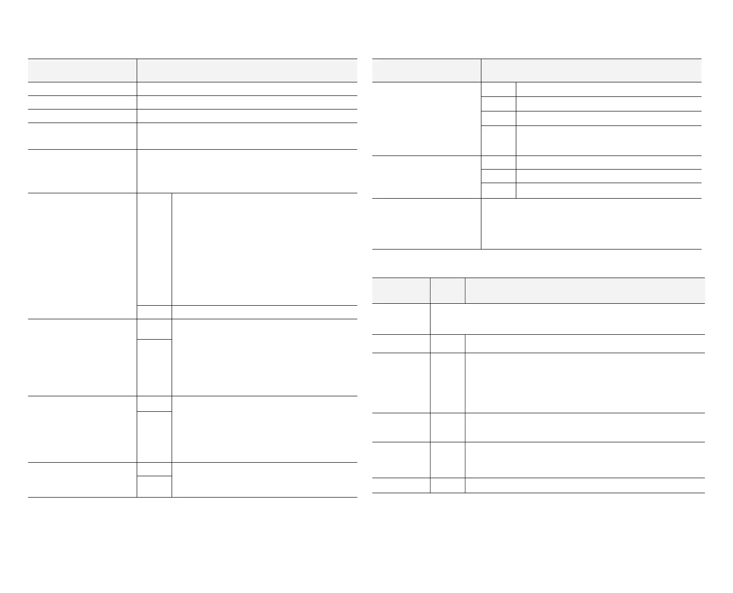
Table 9. Damper Control Connections, Insertion Bridge
and Jumpers
Damper Control Label Description
i+ RSBus data positive
I- RSBus data negative
R RSBus 24VAC power
DMPR XFMR / SYS XFMR Use factory default position.
DMPR XFMR
Connect zone damper 24VAC transformer wires to terminals
DMPR R and XFMR C (see “Figure 3. Conrming Correct
Transformer Phasing” on page 6). Factory default is
DMPR XFMR.
G
SENSE
Connect the IAQ device requiring blower operation
to the indoor unit control G terminal as illustrated
in the wiring diagrams located in the applicable
iComfort Series Thermostat Installer Guide.
Place a wire jumper between the indoor unit G
and damper control module G sense terminals.
This will allow the damper control module to adjust
the indoor blower CFM from continuous blower
speed to the correct zone heating or cooling blower
speed when any zone has a demand for heating or
cooling.
24VAC 24VAC power (NOT USED)
FREEZESTAT
SENSE
From the factory, an insertion bridge is installed
between these two terminals. If a freezestat is to
be used, remove insertion bridge and replace with
connections to freezestat. See table 3 on page 5
for ordering freezestat. NOTE: If jumper is missing
and no freezestat is installed the outdoor unit will
not operate.
24VAC
PRESSURE SW
SENSE
A HFC-410A high pressure switch (catalog number
27W13) is required for applications with a Lennox
heat pump. This switch acts as a guard in case of
high head pressures during rst- and second-stage
heating. The switch opens at 550 psig (3965 kPa)
and closes (resets) at 425 psig (3102 kPa).
24VAC
DATS
SENSE
Terminals for the included discharge air temperature
sensor (DATS). See gure 3 for installation require-
ments.
24VAC
Table 9. Damper Control Connections, Insertion Bridge
and Jumpers
Damper Control Label Description
ZONE 5 (not used), ZONE
2/6, ZONE 3/7 and ZONE
4/8
(NOTE: ONLY ZONE
CONNECTIONS
2, 3 and 4) are used.)
PWR 12VDC power.
D+ Data positive
D- Data negative
C 12VDC common
DAMPER 1/5, DAMPER
2/6, DAMPER 3/7 and
DAMPER 4/8
NC Normally closed.
NO Normally opened.
DCOM Common
ZONE 1 - 4 / 5 - 8
The factory default for this jumper is 1-4. Do not set jumper to
5-8, which is not is supported at this time. The damper control
module only supports zones 1 through 4. Zone one being the
iComfort Wi-Fi or S30 thermostat, and 2 through 4 actually
being remote locations throughout the home.
Table 10. LEDs
LED Indicator
Label/Name
Color Description
DMPR1, 2, 3, 4
Damper position LED. Illuminated when damper is power closed. LED will
remain ON as as long as the damper is power-closed.
CNTRL Red Illuminated when system zoning is OFF.
STATUS Green
This green LED should blink at 1Hz, 50% duty cycle as a
”heartbeat” indicating that the device is operat ing normally.
During device soft disable state, this LED will blink 3 seconds ON
and 1 second OFF. See “Table 10. LEDs” on page 13 for further
details.
RSBUS COMM Green
RSBus activity. Active communications with external device
(Lennox communicating external device).
IN-ZONE
THERMOSTAT
COMM
Green Active communication with in-zone thermostats.
PS Red Illuminate when pressure switch is open (high pressure detected).
 Loading...


