Page 27
TABLE 10
KGA150 NORMAL OPERATING PRESSURES
Outdoor
Coil
Entering
Air Temp
CIRCUIT 1 CIRCUIT 2
Dis
charge
+
10 psig
Suction
+
5 psig
Dis
charge
+
10 psig
Suction
+
5 psig
655 F 279 132 283 136
755 F 318 134 323 138
855 F 360 136 364 139
955 F 406 138 411 140
1055 F 456 141 462 142
1155 F 508 145 515 145
Charge Verification - Approach Method - AHRI Testing
1- Using the same thermometer, compare liquid tempera
ture
(at condenser outlet) to outdoor ambient tempera
ture.
Approach Temperature = Liquid temperature minus
ambient temperature.
2- Approach temperature should match values shown in
table 11. An approach temperature greater than
this val
ue
indicates an undercharge. An approach tempera
ture less than
this value indicates an overcharge.
3- The approach method is not valid for grossly over
charged or undercharged systems.
Use tables 7
through 10
as a guide for typical operating pressures.
TABLE 11
APPROACH TEMPERATURE
Unit
Liquid Temp. Minus Ambient Temp.
1st Stage 2nd Stage
092 9°F + 1 (5.0°C + 0.5) 8°F + 1 (4.4°C + 0.5)
102 7°F + 1 (3.9°C + 0.5) 6°F + 1 (3.3°C + 0.5)
120 8°F + 1 (4.4°C + 0.5) 6°F + 1 (3.3°C + 0.5)
150 6°F + 1 (3.3°C + 0.5) 6°F + 1 (3.3°C + 0.5)
V- SYSTEMS SERVICE CHECKS
A-Heating System Service Checks
All KGA units are ETL/CSA design certified without mod
ification.
Before checking piping, check with gas company or au
thorities having jurisdiction for local code requirements.
Refer to the KGA Installation instruction for more infor
mation.
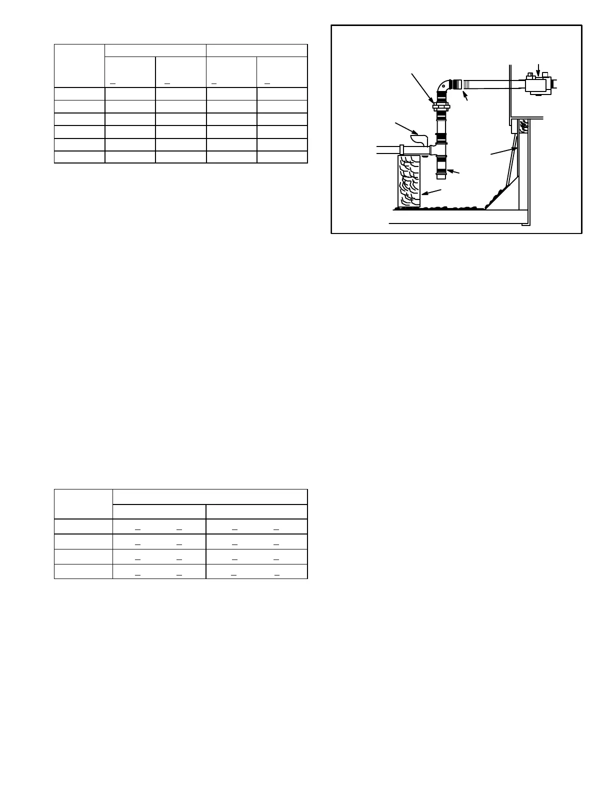
UNIT
GROUND
JOINT UNION
MANUAL MAIN
SHUT-OFF VALVE
(REFER TO LOCAL CODES)
GAS PIPING
SUPPORT
DRIP LEG
ROOF
MOUNTING
FRAME
GAS PIPING COMPONENTS
REFER TO INSTALLATION INSTRUCTIONS
VALVE
CAP HERE TO
ISOLATE VALVE
WHEN PRESSURE
TESTING LINE
FIGURE 20
1-Gas Piping
Gas supply piping must not allow more than 0.5”W.C.
(124.3 Pa) drop in pressure between the gas meter and
the unit. Supply gas pipe must not be smaller than the unit
gas connection. Refer to installation instructions for de
tails.
2-Testing Gas Piping
NOTE-In case emergency shutdown is required, turn off
the main manual shut‐off valve and disconnect the main
power to the unit. These controls should be properly la
beled by the installer.
When pressure testing gas lines, the gas valve must be dis
connected and isolated. Gas valves can be damaged if
subjected to more than 0.5 psig [14”W.C. (3481 Pa)]. See
figure 20.
When checking piping connection for gas leaks, use the
preferred means. Common kitchen detergents can
cause harmful corrosion on various metals used in gas
piping. The use of specialty Gas Leak Detector is strong
ly recommended. It is available as part number
31B2001. See CORP 8411-L10, for further details.
Do not use matches, candles, flame or any other source of
ignition to check for gas leaks.
3-Testing Gas Supply Pressure
When testing gas supply pressure, connect test gauge to the
inlet pressure tap located on unit gas valve GV1. Test sup
ply gas pressure with unit firing at maximum rate (both
stages energized). Make sure the reading falls within the
range of the following values. Low pressure may result in
erratic operation or “underfire.” High pressure can result in
permanent damage to the gas valve or “overfire.” For nat
ural gas units, operating pressure at the unit gas connec
tion must be between 4.7”W.C. and 10.5”W.C. (1168 Pa
and 2610 Pa). For L.P. gas units, operating pressure at
the unit gas connection must be between 10.8”W.C. and
13.5”W.C. (2685.3 Pa and 3356.7 Pa).
 Loading...
