Page 18
TABLE 4
MANUFACTURER'S NUMBERS
DRIVE
NO.
DRIVE COMPONENTS
ADJUSTABLE SHEAVE FIXED SHEAVE BELT
BROWNING NO. OEM PART NO. BROWNING NO. OEM PART NO. BROWNING NO. OEM PART NO.
1 1VP34x7/8 31K6901 AK61x1 100244-20 AX54 100245-25
2 1VP40x7/8 79J0301 AK59x1 31K6801 AX55 100245-26
3 1VP34x7/8 31K6901 AK46x1 100244-17 AX52 100245-33
4 1VP44x7/8 53J9601 AK74x1 100244-21 AX58 100245-34
5 1VP50x7/8 98J0001 AK69x1 37L4701 AX58 100245-34
6 1VP50x7/8 98J0001 AK64x1 12L2501 AX57 100245-28
10 1VP50x1-1/8 P-8-1977 BK77x1 49K4001 BX59 59A5001
11 1VP50x1-1/8 P-8-1977 BK67x1 100244-24 BX57 78L5301
12 1VP50x1-1/8 P-8-1977 BK62x1 100244-23 BX56 100245-11
Cooling Start-Up
IMPORTANT
If unit is equipped with a crankcase heater. Make
sure heater is energized 24 hours before unit start-
up to prevent compressor damage as a result of
slugging.
A-Operation
Supply Air Inverter Units - Refer to the Inverter
Start-Up section for further instruction on blower
control. See table 18 for full details on unit operation.
Compressor 1 is a two-stage compressor. Compressor 2
is a single-stage compressor.
1- Initiate first, second, and third stage cooling demands
according to instructions provided with thermostat.
2- No Economizer Installed in Unit -
See table 5 for cooling operation.
Units Equipped With Economizer -
When outdoor air is suitable, any combination of
thermostat demands will energize the economizer.
See table 6 for cooling operation.
TABLE 5
COOLING OPERATION - NO ECONOMIZER
T'Stat Compressors OD Fans
Y1 Compr. 1 Low Both On
Y1 + Y2 Compr. 1 Low; Compr. 2 On Both On
Y1 + Y2 + Y3 Compr. 1 High; Compr. 2 On Both On
TABLE 6
COOLING OPERATION - WITH ECONOMIZER
T'Stat Compressors OD Fans
Y1 Off Off
Y1 + Y2 Compr. 1 Low Both On
Y1 + Y2 + Y3 Compr. 1 High Both On
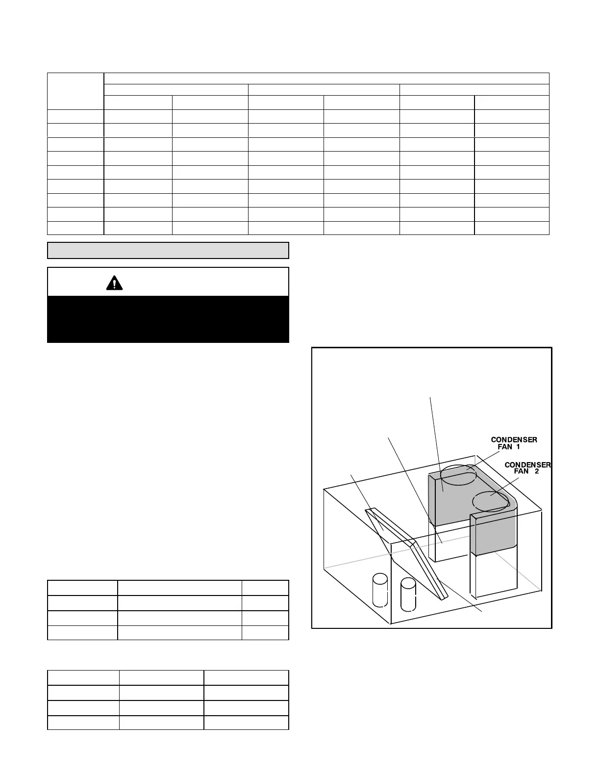
3- Units contain two refrigerant circuits or stages. See
figure 18 or 19.
4- Each refrigerant circuit is separately charged with
R-410A refrigerant. See unit rating plate for correct
amount of charge.
5- Refer to Cooling Operation and Adjustment section for
proper method to check refrigerant charge.
FIGURE 18
REFRIGERANT STAGES - 092, 102, 120, 150
1
2
(BOTH FANS ARE ENERGIZED
WITH A Y1 DEMAND)
CONDENSER COIL
KG/KC 092, 102 - Stage 2
KG/KC 120, 150 - Stage 1
EVAPORATOR
COIL STAGE 1
CONDENSER COIL
KG/KC 092, 102 - Stage 1
KG/KC 120, 150 - Stage 2
EVAPORATOR
COIL STAGE 2

 Loading...

