Page 12
2- Install thermostat assembly in accordance with
instructions provided with thermostat.
3- Connect thermostat wiring to the bottom of the Unit
Controller.
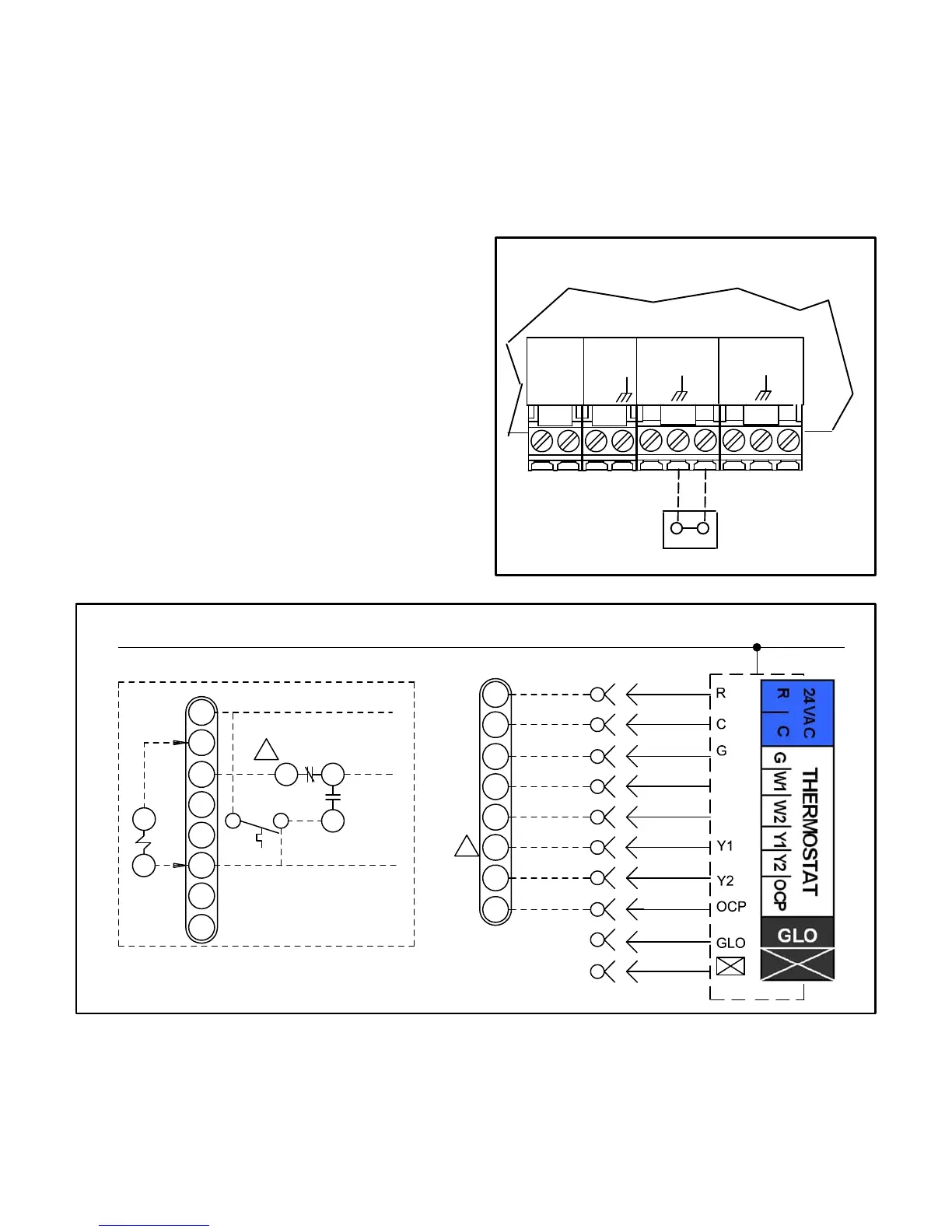
4- Wire as shown in figure 14 for electro-mechanical
and electronic thermostats. If using other
temperature control devices or energy management
systems see instructions and wiring diagram
provided by manufacturer.
IMPORTANT-Terminal connections at the Unit Controller
must be made securely. Loose control wire connections
may allow unit to operate but not with proper response to
room demand.
Room Sensor Mode
The Unit Controller will operate heating and cooling
based on the Unit Controller internal setpoints and the
temperature from the A2 room sensor. An optional
Network Control Panel (NCP) can also be used to provide
setpoints. A thermostat or return air sensor can be used
as a back-up mode. Make room sensor wiring
connections as shown in figure 13.
C-Hot Gas Reheat Units Only -
1- Install humidity sensor in accordance with
instructions provided with sensor. A DDC input may
be used to initiate dehumidification instead of a
sensor.
2- Make wiring connections as shown in figure 14 for
thermostat mode or figure 13 for room sensor
mode. In addition, connect either a humidity
sensor or a dehumidification input. See figure 15
or 16 for humidity sensor wiring or figure 17 for
dehumidification input wiring.
FIGURE 13
FIELD WIRING IN ROOM SENSOR MODE
(Room Sensor Mode)
A2 SENSOR
OUTPUTS
SENSOR
SENSOR
24VAC
RC
IAQ
HUM
AI1
D01
TMP
D02
UNIT CONTROLLER
J298
FIGURE 14
24 VOLT FIELD WIRING IN THERMOSTAT MODE
K55
B
A
K55−1
7
5
2
S86
J262C
10
11
12
P297
J297A
1
2
B
3
4
5
6
7
8
C
9
10
R
OCP
C
G
W1
W2
Y1
Y2
24 V POWER
W1
W2
P262
A55
R
OCP
C
G
W1
W2
Y1
Y2
TO R
TO G
TO Y1
TO PROVIDE SUPERMARKET REHEAT SCHEME
USE S86 DEHUMIDISTAT AND K55.
ALL OTHER THERMOSTAT
SIGNALS REMAIN CONNECTED
AS SHOWN ON THE RIGHT.
TO UNIT CONTROLLER
2
2
THERMOSTAT INPUTS

 Loading...


