EasyManua.ls Logo

Lennox LGH092H

Lennox LGH092H
50 pages
To Next Page IconTo Next Page
Loading...
2015
Litho U.S.A.
WARNING
Improper installation, adjustment, alteration, ser
vice or maintenance can cause property damage,
personal injury or loss of life. Installation and ser
vice must be performed by a licensed professional
HVAC installer or equivalent, service agency, or the
gas supplier
CAUTION
Danger of sharp metallic edges. Can cause injury.
Take care and wear protective clothing when
servicing unit to avoid accidental contact with
sharp edges.
Table Of Contents
Dimensions Page 2.................................
Parts Arrangements Page 4.........................
Shipping and Packing List Page 5....................
General Page 5....................................
Safety Page 5.....................................
Unit Support Page 6................................
Duct Connection Page 7............................
Rigging Unit For Lifting Page 7.......................
Condensate Drains Page 7..........................
Gas Piping Page 9.................................
Pressure Test Gas Piping Page 10.....................
High Altitude Derate Page 11.........................
Electrical Connections Page 11.......................
Blower Operation and Adjustments Page 14............
INSTALLATION
INSTRUCTIONS
LGH092H, LCH092H
LGH094U, LCH094U
LGH102H, LCH102H
LGH120H, LCH120H
LGH122U, LCH122U
LGH150S, LCH150S
LGH152U, LCH152U
(7.5 Ton)
(7.5 Ton)
(8.5 Ton)
(10 Ton)
(10 Ton)
(12.5 Ton)
(12.5 Ton)
PACKAGED UNITS
507245-02
9/2015
Supersedes 507245-01
Cooling Start-Up Page 22............................
Gas Heat Start-Up Page 34...........................
Heating Operation and Adjustments Page 35............
Electric Heat Start-Up Page 35........................
Supply Air Inverter Start-Up Page 36...................
Supply Air Inverter and Direct Drive Operation Page 38...
Direct Drive Start-Up Page 38.........................
Hot Gas Reheat Operation and Start-Up Page 40........
Service Page 41....................................
Unit Controller Parameter Settings Page 45.............
RETAIN THESE INSTRUCTIONS FOR FUTURE REFERENCE
LGH SHOWN
3
3
Question and Answer IconNeed help?

Do you have a question about the Lennox LGH092H and is the answer not in the manual?

Lennox LGH092H Specifications

General IconGeneral
BrandLennox
ModelLGH092H
CategoryAir Conditioner
LanguageEnglish

Summary

Dimensions

End View

Provides dimensional details of the unit's end profile.

Top View

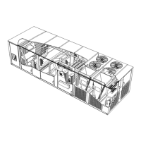
Displays the unit's dimensions and layout from a top perspective.

Side View

Details the unit's dimensions and features from a side profile.

Parts Arrangement

General Information & Safety

Shipping and Packing List

Details the contents of the unit's packaging and shipping.

Unit Clearances

Specifies required clearances around the unit for installation and service.

Safety Warnings

Highlights critical safety precautions and hazards associated with the unit.

Unit Support & Mounting

Downflow Discharge Application

Instructions for supporting units in downflow discharge configurations.

Installers Roof Mounting Frame

Guidelines for using or selecting a roof mounting frame for unit installation.

Ducting, Rigging & Drainage

Duct Connection

Procedures for properly connecting ductwork to the unit.

Rigging Unit For Lifting

Instructions and safety for lifting and moving the unit.

Condensate Drains

Guidance on making condensate drain connections and trap requirements.

Gas Piping Installation

Connect Gas Piping

Steps and requirements for connecting the unit's gas supply piping.

Pressure Test Gas Piping

Procedures for safely pressure testing gas piping connections.

Electrical & Control Wiring

High Altitude Derate

Information on adjusting unit performance for high altitude installations.

Electrical Connections

Instructions for making power supply and wiring connections to the unit.

Thermostat Location

Guidelines for selecting an optimal location for the room thermostat.

Control Wiring

General instructions for connecting unit controls and thermostat wiring.

Control Wiring Details

Thermostat Mode

Wiring instructions for connecting standard thermostats to the unit controller.

Room Sensor Mode

Wiring procedures for using a room sensor to control the unit.

Hot Gas Reheat Units

Specific wiring requirements for units with hot gas reheat functionality.

Blower Operation & Adjustments

Blower Operation

Overview of blower operational modes and thermostat control.

Blower Access

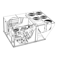
Procedures for accessing the blower assembly for service.

Determining Unit CFM

Methods for calculating and verifying unit airflow (CFM) based on specs.

Blower Belt Adjustment

Instructions for proper alignment and tensioning of blower belts.

Check Belt Tension

Guidelines for checking and verifying correct blower belt tension.

Cooling Start-Up Procedures

Preliminary Checks

Essential checks to perform before initiating unit start-up.

Start-Up

Step-by-step guide for starting the unit's cooling operation.

Refrigerant Information

R410 A Refrigerant

Details on R410A refrigerant properties, pressures, and handling.

Refrigerant Charge and Check

Compressor Controls

Units Equipped With Two Fans

Control logic for units with two condenser fans based on conditions.

Units Equipped With Three Fans

Control logic for units with three condenser fans based on conditions.

Gas Heat Start-Up

Placing Unit In Operation

Initial steps for putting the gas heating unit into operation.

Turning Off Gas to Unit

Procedures for safely shutting off the gas supply to the unit.

Heating Operation & Adjustments

Heating Sequence of Operation

Describes the step-by-step process of the unit's heating cycle.

Limit Controls

Information on factory-set limit controls and their function.

Heating Adjustment

Details on adjusting heating parameters like manifold pressure.

Electric Heat Start-Up

Procedures for starting up electric heating options.

SCR Electric Heat Controller

Setup and adjustment for the SCR controller in electric heat systems.

Inverter Blower Start-Up

Design Specifications

Inputting design specified blower CFM values into the unit controller.

Set Maximum CFM

Determining and setting the highest blower CFM for unit operation.

Enter Design Specifications Into Controller

Navigating the unit controller menu to input blower CFM settings.

Set Damper Minimum Position

Configuring minimum damper positions for ventilation air volumes.

Inverter Bypass Option

Instructions for configuring or bypassing the inverter VFD.

Inverter & Direct Drive Operation

Two-Stage Thermostat

Cooling operation sequence with a two-stage thermostat.

Three-Stage Thermostat OR Room Sensor

Cooling operation sequence with a three-stage thermostat or room sensor.

Direct Drive Blower Start-Up

Set Blower Speed

Setting the desired blower speed based on design CFM and static pressure.

Set Damper Minimum Position

Configuring minimum damper positions for ventilation in direct drive systems.

Hot Gas Reheat Operation

General

Introduction to the hot gas reheat mode and its functionality.

Reheat Coil Solenoid Valve

Operation of the solenoid valve controlling hot gas to the reheat coil.

Reheat Setpoint

How to adjust the setpoint for energizing the reheat function.

Check-Out

Procedure for testing and verifying hot gas reheat operation.

Default Reheat Operation

Default operational modes for reheat based on thermostat demands.

Service & Maintenance

Filters

Guidelines for inspecting, cleaning, and replacing air filters.

Lubrication

Information on motor lubrication requirements.

Gas Burners & Inducer

Burners (Gas Units)

Inspection, cleaning, and adjustment of gas burners.

Combustion Air Inducer (Gas Units)

Maintenance and cleaning procedures for the combustion air inducer.

Heat Exchanger Components

Flue Passageway and Flue Box

Cleaning and maintenance of the unit's flue passageway and box.

Gas Heat Exchanger Inserts

Information regarding the installation and function of heat exchanger inserts.

Unit Components

Evaporator Coil

Cleaning and inspection procedures for the evaporator coil.

Condenser Coil

Maintenance and cleaning guidelines for the condenser coil.

Supply Air Blower Wheel

Inspection and cleaning of the supply air blower wheel.

Compressor

Notes on compressor replacement and internal protectors.

Factory Unit Controller Settings

Units With BACnet Module Settings

Configuration settings for units using a BACnet network module.

Units With Room Sensor, CPCLSE Gateway Settings

Settings for units utilizing room sensors or CPC/LSE gateways.

Units With BACnet Module (Target) Settings

Target settings for units integrated with a BACnet module.

Related product manuals