Page 1
UNIT INFORMATIONUNIT INFORMATION
Service Literature
WARNING
To prevent serious injury or death:
1- Lock-out/tag-out before performing maintenance.
2- If system power is required (e.g., smoke detector
maintenance), disable power to blower, remove
fan belt where applicable, and ensure all
controllers and thermostats are set to the “OFF”
position before performing maintenance.
3- Always keep hands, hair, clothing, jewelry, tools,
etc., away from moving parts.
CAUTION
As with any mechanical equipment, contact with
sharp sheet metal edges can result in personal
injury. Take care while handling this equipment and
wear gloves and protective clothing.
WARNING
Improper installation, adjustment, alteration,
service or maintenance can cause property damage,
personal injury or loss of life. Installation and service
agency.
WARNING
Electric shock hazard. Can cause injury
or death. Before attempting to perform
any service or maintenance, turn the
electrical power to unit OFF at disconnect
switch(es). Unit may have multiple power
supplies.
Table of Contents
Options / Accessories . . . . . . . . . . . . . . . . . . . . . Page 2
Blower Data . . . . . . . . . . . . . . . . . . . . . . . . . . . . . Page 15
Electrical Data . . . . . . . . . . . . . . . . . . . . . . . . . . . Page 18
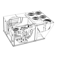
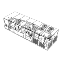
I-Unit Components . . . . . . . . . . . . . . . . . . . . . . . Page 23
II-Placement and Installation . . . . . . . . . . . . . . . Page 46
III-Charging . . . . . . . . . . . . . . . . . . . . . . . . . . . . . . Page 46
V-System Service Checks . . . . . . . . . . . . . . . . . Page 83
VI-Maintenance . . . . . . . . . . . . . . . . . . . . . . . . . Page 86
VII-Accessories. . . . . . . . . . . . . . . . . . . . . . . . . . Page 87
The LGH156H, 180H, 180U, 210H, 240H, 240U, 300S
units (CTO) with a wide selection of factory installed op-
tions.
LGH156H is available in 260,000 Btuh or 360,000 Btuh
(76.2 or 105.5 kW) and has the option for single stage
LGH180H, 180U, 210H, 240H, 240U, 300S and 300U
units are available in 260,000, 360,000 or 480,00 Btuh
(76.2, 105.5 or 140.7 kW) heating inputs.
The LGH180H/U and 210H also has an optional single
Gas heat sections are designed with aluminized steel tube
heat exchangers with stainless steel as an option.
Cooling capacities range from 13 to 25 tons (45.7 to 88
kW). LGH156H, 180H, and 210H utilize three compres-
sors while LGH180U, 240H, 240U, 300S and 300U utilize
four compressors.
Units are designed for R410A refrigerant. See unit name-
plate. Operating pressures and pressure switch settings
equipment must be rated for R410A.
Multi-Stage Air Volume MSAV
®
blower option is available.
The VFD-driven blower will operate at lower speeds when
demand is low and increase to higher speeds when de-
mand is high.
Variable speed VAV system is available as an option which
enables supply duct static measurement to control blow-
er CFM and discharge air temperature to control cooling
stages.
-
ent energy management thermostat control systems with
-
tions connect to the unit through Smartwire connectors.
When “plugged in” the controls become an integral part of
the unit wiring.
Information contained in this manual is intended for use
subject to change. Procedures outlined in this manual are
presented as a recommendation only and do not super-
sede or replace local or state codes.
If the unit must be lifted for service, rig unit by attaching
four cables to the holes located in the unit base rail (two
holes at each corner). Refer to the installation instructions
for the proper rigging technique.
LGH SERIES
13 to 25 ton
45.7 to 88 kW
Copr 1013-L2
Revised 05/2020
LGH156H through 300U