EasyManua.ls Logo

Lennox LGH120H

Lennox LGH120H
92 pages
To Next Page IconTo Next Page
Loading...
Corp. 1008-L2
LGH SERIES
Service Literature
7.5 to 12.5 ton
38.1 to 70.3 kW
Revised 05/2020
LGH092H through 152U
The LGH092H, 094U, 102H, 120H, 122U, 150S, 150H
and 152U units are configure to order units (CTO) with a
wide selection of factory-installed options. Units are
available in 130,000, 180,000 Btuh or 240,000 Btuh
(38.1, 52.7 or 70.3 kW) heating inputs. Gas heat sec
tions are designed with aluminized steel tube heat ex
changers with stainless steel as an option.
Cooling capacities range from 7.5 to 12.5 tons (38.1 to
70.3 kW). All units are equipped with two compressors.
Ultra-high efficiency units are available with an optional di
rect drive blower or belt drive blower equipped with a sup
ply air inverter. Standard and high efficiency units are
available with a belt drive blower equipped with an option
al supply air inverter. The blower will operate at lower
speeds when demand is low and increase to higher
speeds when demand is high.
The following examples show the model numbers of ten-
ton units with all available blower options:
LGH120H4B High Efficiency Belt Drive
LGH120H4M High Efficiency Belt Drive with Inverter
LGH122U4M Ultra High Efficiency Belt Drive with Inverter
LGH122U4E Ultra High Efficiency Direct Drive
Note - Ten-ton units are available in high and ultra high effi
ciencies only.
Standard and high efficiency units come standard with a
lightweight, all-aluminum condenser coil; optional, fin/
tube condenser coils are available. Ultra-high efficiency
units come standard with a tube/fin condenser coil.
Ultra high efficiency units come standard with two single-
speed compressors plumbed in tandem to form a single re
frigerant circuit.
Units are also designed for R410A refrigerant. See unit
nameplate. Operating pressures and pressure switch set
tings are significantly higher than R22 charged units. Ser
vice equipment must be rated for R410A.
Standard and high efficiency units offer mechanical cooling
down to 0°F when properly equipped. Ultra-high efficiency
units offer mechanical cooling down to 40°F.
All LGH units are designed to accept any of several differ
ent energy management thermostat control systems with
minimum field wiring. Factory or field provided control op
tions connect to the unit with jack plugs. When ”plugged in”
the controls become an integral part of the unit wiring.
Information contained in this manual is intended for use by
qualified service technicians only. All specifications are
subject to change. Procedures outlined in this manual are
presented as a recommendation only and do not super
sede or replace local or state codes.
If the unit must be lifted for service, rig unit by attaching four
cables to the holes located in the unit base rail (two holes at
each corner). Refer to the installation instructions for the
proper rigging technique.
3
3
Table of Contents
Options / Accessories Page 2.....................
Specifications Page 8............................
Blower Tables Page 14............................
Electrical Data Page 19...........................
Parts Arrangement Page 25.......................
I-Unit Components Page 28.......................
II-Placement and Installation Page 47...............
III-Charging Page 47..............................
IV-Start Up - Operation Page 55....................
V-System Service Checks Page 57................
High Altitude Page 59.........................
VI-Maintenance Page 59..........................
VII-Accessories Page 60..........................
VIII-Belt Drive Supply Air Inverter Page 67...........
IX-Direct Drive Supply Air Blower Page 70...........
X-Staged Supply Air Operation Page 71.............
XI-Wiring and Operation Sequence Page 72.........
WARNING
Improper installation, adjustment, alteration, service
or maintenance can cause property va, personal in
jury or loss of life. Installation and service must be
performed by a licensed professional HVAC installer
or equivalent, service agency, or the gas supplier
CAUTION
As with any mechanical equipment, contact with
sharp sheet metal edges can result in personal in
jury. Take care while handling this equipment and
wear gloves and protective clothing.
© 2019

Other manuals for Lennox LGH120H

Question and Answer IconNeed help?

Do you have a question about the Lennox LGH120H and is the answer not in the manual?

Lennox LGH120H Specifications

General IconGeneral
Cooling Capacity12000 BTU/h
Heating Capacity12000 BTU/h
RefrigerantR-410A
Phase1
Voltage208/230V

Summary

SPECIFICATIONS

SPECIFICATIONS - 092 H, 102 H

Provides detailed specifications for LGH/LCH092H and 102H models, covering cooling, refrigerant, gas heating, and electrical data.

SPECIFICATIONS 120 H, 150 H

Provides detailed specifications for LGH/LCH120H and 150H models, including cooling, refrigerant, gas heating, and electrical data.

SPECIFICATIONS - GAS HEAT - 092 H, 102 H, 120 H, 150 H

Details gas heating performance specifications, including input/output Btuh, temp rise, thermal efficiency, and gas supply connections.

SPECIFICATIONS - DIRECT DRIVE MODELS

Provides specifications for direct drive models LGH094U4E, LGH122U4E, and LGH152U4E, covering cooling, refrigerant, and electrical data.

SPECIFICATIONS - BELT DRIVE MODELS - 094 U, 122 U, 152 U

Provides specifications for belt drive models LGH094U4M, LGH122U4M, and LGH152U4M, covering cooling, refrigerant, and electrical data.

SPECIFICATIONS - GAS HEAT - 094 U, 122 U, 152 U

Details gas heating performance specifications for LGH/LCH094U, 122U, 152U models, including input/output Btuh and gas supply connections.

ELECTRICAL DATA

7.5 HIGH EFFICIENCY (R-410 A)

Electrical data for 7.5 ton high efficiency units, including voltage, compressor amps, and motor specs.

8.5 HIGH EFFICIENCY (R-410 A)

Electrical data for 8.5 ton high efficiency units, detailing voltage, compressor amps, and motor specifications.

10 HIGH EFFICIENCY (R-410 A)

Electrical data for 10 ton high efficiency units, covering voltage, compressor, and motor electrical parameters.

12.5 HIGH EFFICIENCY (R-410 A)

Electrical data for 12.5 ton high efficiency units, listing voltage, compressor amps, and motor specs.

DIRECT DRIVE, 7.5, LGH094 U4 E

Electrical data for 7.5 ton direct drive units, including voltage, compressor, and motor load data.

DIRECT DRIVE, 10, LGH122 U4 E

Electrical data for 10 ton direct drive units, detailing voltage, compressor amps, and motor specifications.

DIRECT DRIVE, 12.5, LGH152 U4 E

Electrical data for 12.5 ton direct drive units, specifying voltage, compressor, and motor electrical parameters.

BELT DRIVE, 7.5, LGH094 U4 M

Electrical data for 7.5 ton belt drive units, including voltage, compressor, and motor load information.

BELT DRIVE, 10, LGH122 U4 M

Electrical data for 10 ton belt drive units, detailing voltage, compressor amps, and motor specs.

PARTS ARRANGEMENT

PARTS ARRANGEMENT - 092 H, 102 H, 120 H, 150 S ALL-ALUMINUM COIL SYSTEM

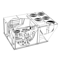
Diagram showing parts arrangement for 092H, 102H, 120H, 150S units with all-aluminum coil system.

PARTS ARRANGEMENT - 092 H, 102 H, 120 H, 150 H FINTUBE COIL

Diagram showing parts arrangement for 092H, 102H, 120H, 150H units with fin/tube coil.

PARTS ARRANGEMENT - 094 U, 122 U, 152 U FINTUBE COIL

Diagram showing parts arrangement for 094U, 122U, 152U units with fin/tube coil.

CONTROL BOX PARTS ARRANGEMENT - STANDARD AND HIGH EFFICIENCY NON-CE UNITS

Diagram showing control box parts arrangement for standard and high efficiency non-CE units.

CONTROL BOX PARTS ARRANGEMENT - ULTRA HIGH EFFICIENCY NON-CE UNITS

Diagram showing control box parts arrangement for ultra high efficiency non-CE units.

CONTROL BOX PARTS ARRANGEMENT - CE UNITS

Diagram showing control box parts arrangement for CE units.

I-UNIT COMPONENTS

12-Unit Controller A55

Overview of the A55 Unit Controller providing unit control functions, status, diagnostics, and parameter settings.

B-Cooling Components

1-Compressors B1, B2

Description of scroll compressors B1 and B2 and their role in cooling circuits.

3-High Pressure Switches S4, S7

Details on auto-reset SPST N.C. high pressure switches S4 and S7 that open on pressure rise.

7-Low Pressure Switches S87, S88

Details on auto-reset SPST N.O. low pressure switches S87 and S88 that open on pressure drop.

ADJUST CFM

D-Set Damper Minimum Position

Procedure for setting minimum damper positions to maintain required ventilation air volumes.

E-VFD Bypass Option

Instructions on how to configure the VFD bypass option for manual or automatic operation.

D-GAS HEAT COMPONENTS

Burner Ignition Control A3

Description of the Johnson Controls burner ignition control, its functions, and sequences.

6-Flame Roll-out Limit S47

Details on the flame roll-out limit switch S47, its location, and function in preventing overheating.

7-Combustion Air Prove Switch S18

Information on the combustion air prove switch S18 that monitors inducer operation and closes on negative pressure.

10-Gas Valves GV1

Information on two-stage redundant gas valves GV1, including types and operation.

III-CHARGING

A-Refrigerant Charge and Check - All-Aluminum Coil

Procedure for checking and verifying refrigerant charge in all-aluminum coil units using pressure and temperature measurements.

B-Refrigerant Charge and Check - FinTube Coil - TXV

Procedure for checking refrigerant charge in fin/tube coil units with TXV, using operating pressures.

Charge Verification - Approach Method - AHRI Testing

Method for verifying charge using approach temperature, comparing liquid temp to ambient temp.

IV-START-UP - OPERATION

A-Preliminary and Seasonal Checks

Pre-start-up checks including electrical, refrigerant lines, voltage, amp draw, and blower belt.

B-Cooling Start-up See figure 34, 35 or 36 for Circuits

Instructions for starting up the cooling mode, referencing refrigerant circuit diagrams.

C-Heating Start-up

Placing Furnace In Operation

Step-by-step procedure for placing the furnace into operation, including gas valve and burner checks.

D-Safety or Emergency Shutdown

Procedures for performing a safety or emergency shutdown of the unit.

V-SYSTEMS SERVICE CHECKS

A-Heating System Service Checks

Procedures for performing heating system service checks, including gas piping and pressure tests.

1-Gas Piping

Guidelines for gas supply piping requirements, including pressure drop and connection size.

2-Testing Gas Piping

Procedures for testing gas piping, emphasizing isolation of the gas valve and pressure limits.

3-Testing Gas Supply Pressure

Instructions for testing gas supply pressure at the unit's inlet, ensuring it falls within specified ranges.

4-Check and Adjust Manifold Pressure

Procedure for checking and adjusting manifold pressure after line pressure is verified and adjusted.

5-Proper Gas Flow

Method to check proper gas flow to burners by determining Btuh input and dividing by gas heating capacity.

7-Spark Electrode Gap

Instructions for checking and setting the spark electrode gap for proper unit operation.

VI-MAINTENANCE

H-Economizer (all units)

P-Factory Installed-Hot Gas Reheat (optional)

VIII-Belt Drive Supply Air Inverter

IX-Direct Drive Supply Air Inverter

X-Staged Supply Air Operation

XI-Wiring Diagrams and Sequence of Operation

LGH092150 SEQUENCE OF OPERATION

LGH092152 U M3 SEQUENCE OF OPERATION

GAS HEAT SEQUENCE OF OPERATION LGH092150

ECONOMIZER

SUPPLY AIR INVERTER - NO BYPASS SEQUENCE OF OPERATION

SUPPLY AIR INVERTER - WITH OPTIONAL FACTORY-INSTALLED BYPASS SEQUENCE OF OPERATION

DIRECT DRIVE BLOWER SEQUENCE OF OPERATION TROUBLESHOOTING

Blower Fault Sequence Direct Drive Motor - No S52:

Troubleshooting steps for direct drive blower motor faults when the S52 switch is not configured.

Blower Fault Sequence Direct Drive Motor - With S52 (If Configured):

Troubleshooting steps for direct drive blower motor faults when the S52 switch is configured.

Failure HandlingTroubleshooting:

General failure handling and troubleshooting steps for direct drive blowers, including clearing delays and checking alarms.

Related product manuals