Corp. 1008-L2
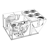
LGH SERIES
Service Literature
7.5 to 12.5 ton
38.1 to 70.3 kW
Revised 05/2020
LGH092H through 152U
The LGH092H, 094U, 102H, 120H, 122U, 150S, 150H
and 152U units are configure to order units (CTO) with a
wide selection of factory-installed options. Units are
available in 130,000, 180,000 Btuh or 240,000 Btuh
(38.1, 52.7 or 70.3 kW) heating inputs. Gas heat sec
tions are designed with aluminized steel tube heat ex
changers with stainless steel as an option.
Cooling capacities range from 7.5 to 12.5 tons (38.1 to
70.3 kW). All units are equipped with two compressors.
Ultra-high efficiency units are available with an optional di
rect drive blower or belt drive blower equipped with a sup
ply air inverter. Standard and high efficiency units are
available with a belt drive blower equipped with an option
al supply air inverter. The blower will operate at lower
speeds when demand is low and increase to higher
speeds when demand is high.
The following examples show the model numbers of ten-
ton units with all available blower options:
LGH120H4B High Efficiency Belt Drive
LGH120H4M High Efficiency Belt Drive with Inverter
LGH122U4M Ultra High Efficiency Belt Drive with Inverter
LGH122U4E Ultra High Efficiency Direct Drive
Note - Ten-ton units are available in high and ultra high effi
ciencies only.
Standard and high efficiency units come standard with a
lightweight, all-aluminum condenser coil; optional, fin/
tube condenser coils are available. Ultra-high efficiency
units come standard with a tube/fin condenser coil.
Ultra high efficiency units come standard with two single-
speed compressors plumbed in tandem to form a single re
frigerant circuit.
Units are also designed for R410A refrigerant. See unit
nameplate. Operating pressures and pressure switch set
tings are significantly higher than R22 charged units. Ser
vice equipment must be rated for R410A.
Standard and high efficiency units offer mechanical cooling
down to 0°F when properly equipped. Ultra-high efficiency
units offer mechanical cooling down to 40°F.
All LGH units are designed to accept any of several differ
ent energy management thermostat control systems with
minimum field wiring. Factory or field provided control op
tions connect to the unit with jack plugs. When ”plugged in”
the controls become an integral part of the unit wiring.
Information contained in this manual is intended for use by
qualified service technicians only. All specifications are
subject to change. Procedures outlined in this manual are
presented as a recommendation only and do not super
sede or replace local or state codes.
If the unit must be lifted for service, rig unit by attaching four
cables to the holes located in the unit base rail (two holes at
each corner). Refer to the installation instructions for the
proper rigging technique.
3
3
Table of Contents
Options / Accessories Page 2.....................
Specifications Page 8............................
Blower Tables Page 14............................
Electrical Data Page 19...........................
Parts Arrangement Page 25.......................
I-Unit Components Page 28.......................
II-Placement and Installation Page 47...............
III-Charging Page 47..............................
IV-Start Up - Operation Page 55....................
V-System Service Checks Page 57................
High Altitude Page 59.........................
VI-Maintenance Page 59..........................
VII-Accessories Page 60..........................
VIII-Belt Drive Supply Air Inverter Page 67...........
IX-Direct Drive Supply Air Blower Page 70...........
X-Staged Supply Air Operation Page 71.............
XI-Wiring and Operation Sequence Page 72.........
WARNING
Improper installation, adjustment, alteration, service
or maintenance can cause property va, personal in
jury or loss of life. Installation and service must be
performed by a licensed professional HVAC installer
or equivalent, service agency, or the gas supplier
CAUTION
As with any mechanical equipment, contact with
sharp sheet metal edges can result in personal in
jury. Take care while handling this equipment and
wear gloves and protective clothing.
© 2019