Page 43
A
B
C
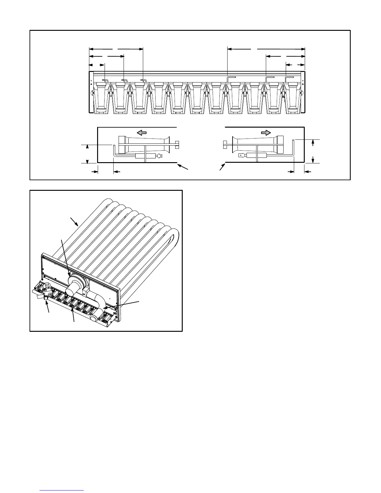
FIGURE 34
IGNITOR AND SENSOR POSITION
TOP VIEW
SIDE VIEW IGNITOR SIDE VIEW SENSOR
1-3/4”
(45mm)
3/8”
(10mm)
1-3/8”
(35mm)
BURNER BOX
Gas Flow
Gas Flow
13/16”
(21mm)
A
B
C
IGNITOR SENSOR
HEAT EXCHANGER ASSEMBLY
FIGURE 35
BURNER
COMBUSTION
AIR INDUCER
VENT
CONNECTOR
GAS VALVE
HEAT
EXCHANGER
TUBE
E-Flue Passageway and Flue Box (Gas Units)
1- Remove combustion air inducer assembly as
described in section D.
2- Remove flue box cover. Clean with a wire brush as
required.
3- Remove inserts if installed. See figure 36.
4- Clean tubes with a wire brush.
5- Reassemble the unit. The flue box cover gasket and
combustion air inducer gasket should also be
replaced during reassembly.
F-Gas Heat Exchanger Inserts
1- Inserts are installed on standard (130,000Btuh) and
high (240,000Btuh) heat exchangers. Medium heat
exchangers do not require inserts. See figure 36.

 Loading...