Page 52
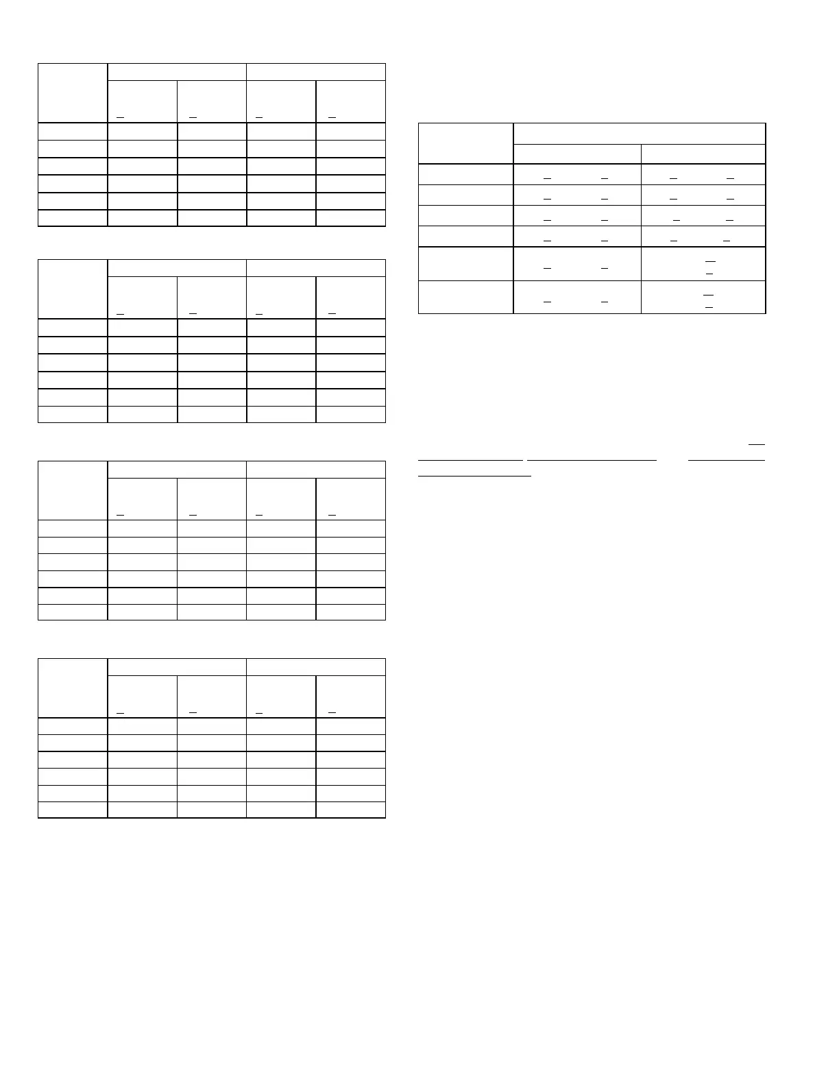
TABLE 15
LGH/LCH150S Fin/Tube Coil - TXV
Outdoor
Coil
Entering
Air Temp
CIRCUIT 1 CIRCUIT 2
Dis
charge
+
10 psig
Suction
+
5 psig
Dis
charge
+
10 psig
Suction
+
5 psig
655 F 275 140 298 139
755 F 312 142 335 141
855 F 354 143 374 142
955 F 398 146 419 146
1055 F 449 149 465 148
1155 F 500 151 514 150
TABLE 16
LGH/LCH150S Fin/Tube Coil Hot Gas Reheat - TXV
Outdoor
Coil
Entering
Air Temp
CIRCUIT 1 CIRCUIT 2
Dis
charge
+
10 psig
Suction
+
5 psig
Dis
charge
+
10 psig
Suction
+
5 psig
655 F 280 136 296 136
755 F 319 141 335 141
855 F 360 142 376 143
955 F 407 144 420 144
1055 F 455 147 466 147
1155 F 510 150 518 150
TABLE 17
LGH/LCH150H Fin/Tube - TXV
Outdoor
Coil
Entering
Air Temp
CIRCUIT 1 CIRCUIT 2
Dis
charge
+
10 psig
Suction
+
5 psig
Dis
charge
+
10 psig
Suction
+
5 psig
65°F 276 131 275 125
75°F 317 133 314 128
85°F 357 136 363 131
95°F 399 139 408 136
105°F 450 142 457 140
115°F 502 145 509 142
TABLE 18
LGH/LCH150H Fin/Tube Hot Gas Reheat - TXV
Outdoor
Coil
Entering
Air Temp
CIRCUIT 1 CIRCUIT 2
Dis
charge
+
10 psig
Suction
+
5 psig
Dis
charge
+
10 psig
Suction
+
5 psig
65° F 296 135 286 135
75° F 334 137 318 136
85° F 378 139 364 138
95° F 422 142 409 140
105° F 470 144 458 142
115° F 520 147 509 146
Charge Verification - Approach Method - AHRI Testing
(Fin/Tube Coil Continued)
1- Using the same thermometer, compare liquid tempera
ture to outdoor ambient temperature.
Approach Temperature = Liquid temperature (at con
denser outlet) minus ambient temperature.
2- Approach temperature should match values in table 19.
An approach temperature greater than value shown indi
cates an undercharge. An approach temperature less
than value shown indicates an overcharge.
3- The approach method is not valid for grossly over or
undercharged systems. Use tables 9 through 18 as a
guide for typical operating pressures.
TABLE 19
APPROACH TEMPERATURE - FIN/TUBE COIL - TXV
Unit
Liquid Temp. Minus Ambient Temp.
1st Stage 2nd Stage
092
6°F + 1 (3.3°C + 0.5) 7°F + 1 (3.9°C + 0.5)
102
6°F + 1 (3.3°C + 0.5) 9°F + 1 (5.0°C + 0.5)
120 & 150S
6°F + 1 (3.3°C + 0.5) 10°F+1 (5.6°C + 0.5)
150H
4°F + 1 (2.2°C + 0.5) 6°F+1 (3.3°C + 0.5)
092, 120 & 150
Hot Gas Reheat
6°F + 1 (3.3°C + 0.5)
8°F + 1
(4.4°C +
0.5)
102
Hot Gas Reheat
6°F + 1 (3.3°C + 0.5)
9°F + 1
(5.0°C +
0.5)
F-Refrigerant Charge and Check - Fin/Tube Coil & RFC
LGH/LCH150S
WARNING-Do not exceed nameplate charge under any
condition.
This unit is factory charged and should require no further
adjustment. If the system requires additional refrigerant, re
claim the charge, evacuate the system, and add required
nameplate charge.
NOTE - System charging is not recommended below 60_F
(15_C). In temperatures below 60_F (15_C), the charge
must be weighed into the system.
If weighing facilities are not available, or to check the
charge, use the following procedure:
IMPORTANT - Charge unit in standard cooling mode.
1- Make sure outdoor coil is clean. Attach gauge manifolds
and operate unit at full CFM in cooling mode with econo
mizer disabled until system stabilizes (approximately five
minutes). Make sure all outdoor air dampers are closed.
2- Check each system separately with all stages operat
ing. Compare the normal operating pressures (see table
20) to the pressures obtained from the gauges. Check
unit components if there are significant differences.
3- Measure the outdoor ambient temperature and the suc
tion pressure. Refer to the appropriate circuit charging
curve to determine a target liquid temperature.
Note - Pressures are listed for sea level applications.
4- Use the same thermometer to accurately measure the
liquid temperature (in the outdoor section).
D If measured liquid temperature is higher than the
target liquid temperature, add refrigerant to the
system.
D If measured liquid temperature is lower than the
target liquid temperature, recover some refrigerant
from the system.
5- Add or remove charge in increments. Allow the system
to stabilize each time refrigerant is added or removed.
6- Continue the process until measured liquid tempera
ture agrees with the target liquid temperature. Do not
go below the target liquid temperature when adjusting
 Loading...
