Page 55
507124-04 3/2016
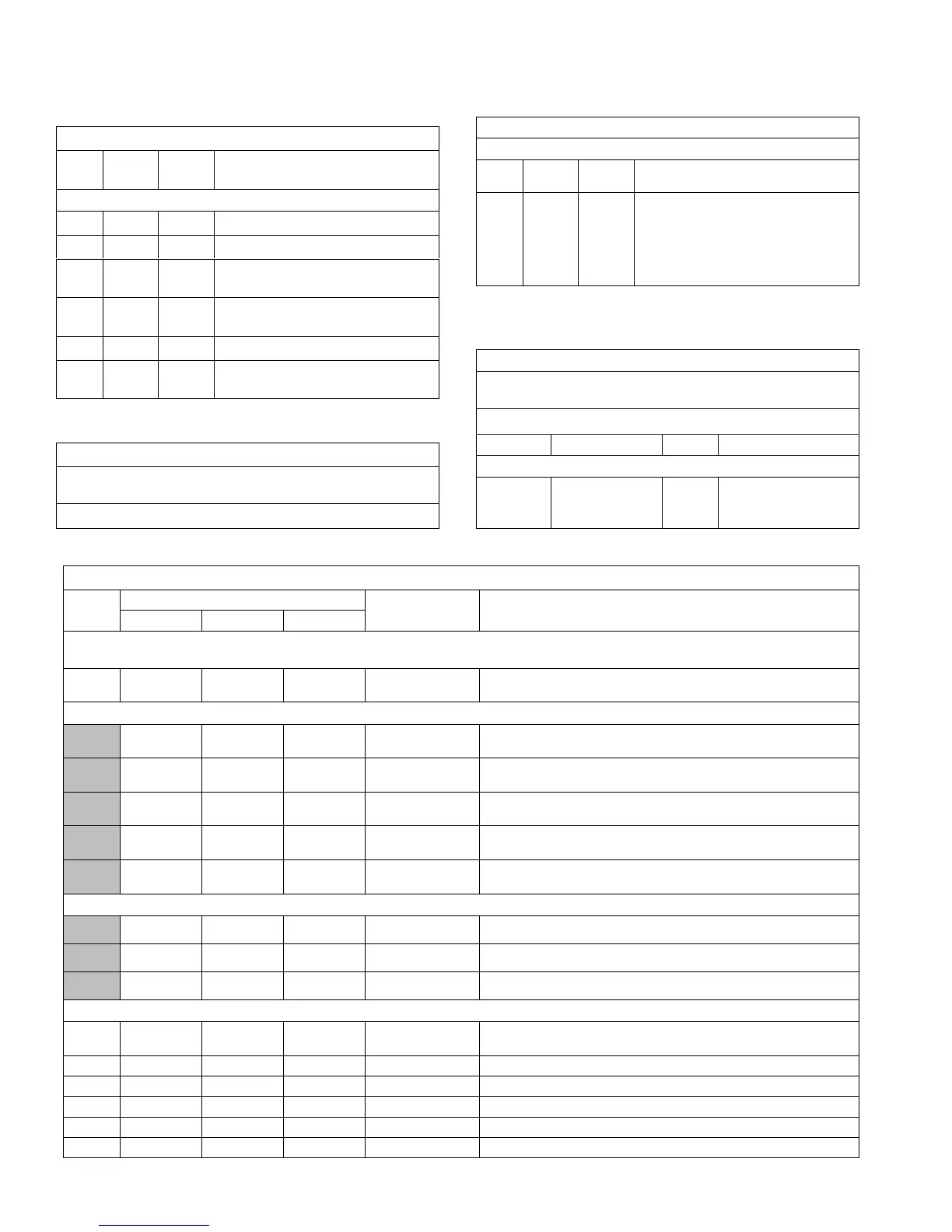
TABLE 29
580731
Units With Automated Logic DDC (Target) Settings
Para
meter
Factory
Setting
Field
Setting
Description
Use SETTINGS > RTU OPTIONS > EDIT PARAMETERS
91 120 Compressor minimum run time.
111 3 Thermostat with three cooling stages.
118 400
Damper “start open” CO
2
setpoint for
DCV.
119 2000
Damper “full open” CO
2
setpoint for
DCV.
139 74 Backup occupied cooling setpoint.
153 60
Time delay between heating and cooling
mode.
TABLE 30
580732
Units With Room Sensor, CPC/LSE Gateway Settings
Use menu SETUP > NETWORK INTEGRATION. Set “L CONNEC
TION” and network address.
LCONN ADDRESS:
TABLE 31
580734
Units With Hot Gas Reheat
Use SETTINGS > RTU OPTIONS > EDIT PARAMETERS
Para
meter
Factory
Setting
Field
Setting
Description
105 6
Hot Gas Reheat Option 6: Reheat is
only possible if blower is energized dur
ing occupied periods. Controlled by RH
sensor (A91) connected to input
A55_P298_5 and set point set at para
meter 106 (default 60%).
TABLE 32
580733
Units With BACnet Module (Kohl's) Settings
Use menu SETUP > NETWORK INTEGRATION. Set “BACNET”
and network address.
BACNET MAC ADDRESS:
Parameter Factory Setting Setting Description
Use SETTINGS > RTU OPTIONS > EDIT PARAMETERS
137 65
Sets the backup occu
pied heating setpoint to
65F.
TABLE 33
580745
LGH/LCH 156H/180H/210H (3-Compressor) MSAV
Para-meter
Factory Setting
Field
Setting
Description
156 180 210
Note: Any changes to Smoke CFM setting must be adjusted before the other CFM settings. Use SETTINGS > RTU OPTIONS > EDIT
PARAMETERS
12
5200
CFM
6000
CFM
7000
CFM
CFM Blower CFM during smoke detection.
SETUP > TEST & BALANCE (can also use SETTINGS > RTU OPTIONS > BLOWER > SPEEDS)
5200
CFM
6000
CFM
7000
CFM
CFM
Blower CFM during heating.
4675
CFM
5400
CFM
6300
CFM
CFM
Blower CFM during compressor 3 operation.
3375
CFM
3900
CFM
4550
CFM
CFM
Blower CFM during compressor 2 operation.
3375
CFM
3900
CFM
4550
CFM
CFM
Blower CFM during compressor 1 operation.
5200
CFM
6000
CFM
7000
CFM
CFM
Blower CFM during ventilation.
SETUP > TEST & BALANCE (can also use SETTINGS > RTU OPTIONS > DAMPER)
0% 0% 0% % Damper min. position during LOW blower operation.
0% 0% 0% % Damper min. position during HIGH blower operation.
50% 50% 50% % Min. damper % for stage 1 power exhaust operation.
SETTINGS > RTU OPTIONS > EDIT PARAMETERS
29 101% 101% 101% %Open
Damper minimum position during G blower operation. (Setting parameter 29 to
“101” disables parameter 29 and passes control to parameter 9 or 132)
219 70% 70% 70% % Min. damper % for stage 2 power exhaust operation.
216 10% 10% 10% % Deadband % for stage 1 power exhaust operation.
220 10% 10% 10% % Deadband % for stage 2 power exhaust operation.
224 100 100 100 Sec Stage 1 power exhaust off-delay in seconds.
30 70% 70% 70% %Speed Minimum blower speed % for stage 2 power exhaust operation.
 Loading...
