Page 56
LGH/LCH156, 180, 210, 240, 300S
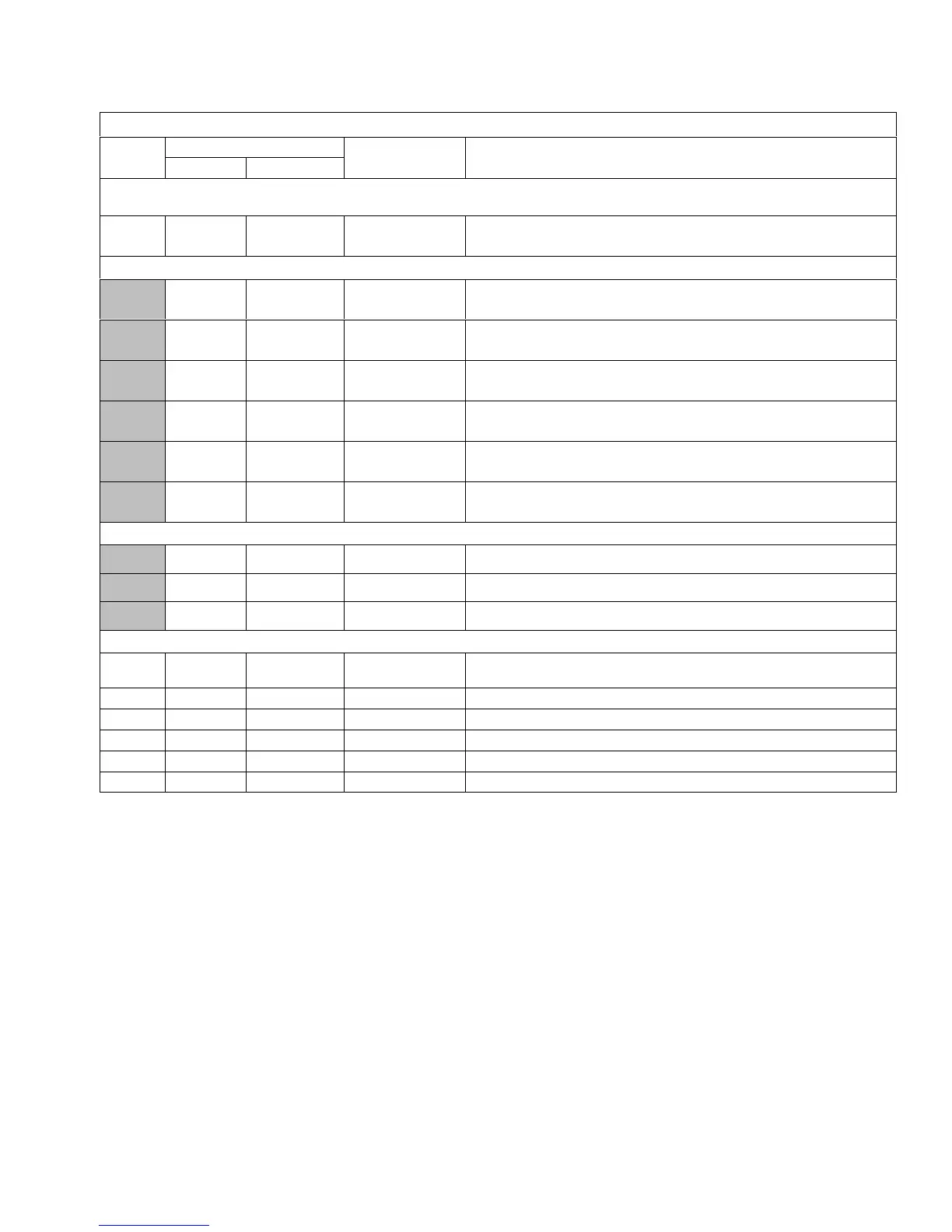
TABLE 34
580746
LGH/LCH 240H/300S (4-Compressor) MSAV
Para-
meter
Factory Setting
Field Setting Description
240S 300S
Note: Any changes to Smoke CFM setting must be adjusted before the other CFM settings. Use SETTINGS > RTU OPTIONS > EDIT
PARAMETERS
12
8000
CFM
10000
CFM
CFM Blower CFM during smoke detection.
SETUP > TEST & BALANCE (can also use SETTINGS > RTU OPTIONS > BLOWER > SPEEDS)
8000
CFM
10000
CFM
CFM
Blower CFM during heating.
7200
CFM
9000
CFM
CFM
Blower CFM during compressor 4 operation.
5200
CFM
6500
CFM
CFM
Blower CFM during compressor 3 operation. This parameter is inactive for thermostats
with 2-stage cooling.
5200
CFM
6500
CFM
CFM
Blower CFM during compressor 2 operation.
5200
CFM
6500
CFM
CFM
Blower CFM during compressor 1 operation. This parameter is inactive for thermostats
with 2-stage or 3-stage cooling.
8000
CFM
10000
CFM
CFM
Blower CFM during ventilation.
SETUP > TEST & BALANCE (can also use SETTINGS > RTU OPTIONS > DAMPER)
0% 0% % Damper min. position during LOW blower operation.
0% 0% % Damper min. position during HIGH blower operation.
50% 50% % Min. damper % for stage 1 power exhaust operation.
SETTINGS > RTU OPTIONS > EDIT PARAMETERS
29 101% 101% %Open
Damper minimum position during G blower operation. (Setting parameter 29 to “101”
disables parameter 29 and passes control to parameter 9 or 132)
219 70% 70% % Min. damper % for stage 2 power exhaust operation.
216 10% 10% % Deadband % for stage 1 power exhaust operation.
220 10% 10% % Deadband % for stage 2 power exhaust operation.
224 100 100 Sec Stage 1 power exhaust off-delay in seconds.
30 70% 70% %Speed Minimum blower speed % for stage 2 power exhaust operation.
 Loading...


