Page 36
11-High Temperature Limit Switch S5, S8, S31 &S180
(180U, 240U & 300U)
These high temperature limit switches are N.C and wired
in series with the compressor contactors. When opened
due to high temperature the compressor contactors are
de-energized, de-energizing the compressors. S5 and S8
are in series with contactors K1 and K2 and compressors
B1and B2. S31 and S180 are in series with contactors
K14 and K146 and compressors B13 and B20. See unit
diagram.
C-Blower Compartment
The blower compartment is located between the evapo-
rator coil and the compressor / control section on the op-
posite side of the condenser coil. The blower assembly is
accessed by disconnecting the blower motor wiring (and
all other plugs) and removing the screws on either side of
1-Blower Wheels
All units have two 15 in. x 15 in. (381 mm x 381 mm) blow-
er wheels. Both wheels are driven by one motor.
2-Indoor Blower Motor B3
All units use three-phase single-speed blower motors.
CFM adjustments are made by adjusting the motor pulley
(sheave). Motors are equipped with sealed ball bearings.
(table of contents) in the front of this manual. Units may
be equipped with motors manufactured by various manu-
your unit.
OPERATION / ADJUSTMENT
Staged-Blower Units - The blower rotation will always be
correct on staged-blower units. Checking blower rotation
is not a valid method of determining voltage phasing for
incoming power.
Staged-Blower Units and Units Equipped With Op-
tional Voltage or Phase Detection - The Unit Controller
checks the incoming power during start-up. If the voltage
or phase is incorrect, the Unit Controller will display an
alarm and the unit will not start.
Variable Air Volume Units - Refer to the Variable Air
Volume Start-Up section.
1 - The following measurements must be made with
a dry indoor coil. Run blower (G demand) without
a cooling demand. Measure the indoor blower
measurements are taken.
2 - With all access panels in place, measure static
pressure external to unit (from supply to return).
Blower performance data is based on static pressure
Note - Static pressure readings can vary if not taken
where shown.
3 - Referring to page 17, use static pressure and RPM
readings to determine unit CFM. Use page 18 when
installing units with any of the optional accessories
listed.
4 - The blower RPM can be adjusted at the motor pulley.
Loosen Allen screw and turn adjustable pulley
clockwise to increase CFM. Turn counterclockwise
minimum and maximum number of pulley turns as
shown in table 5.
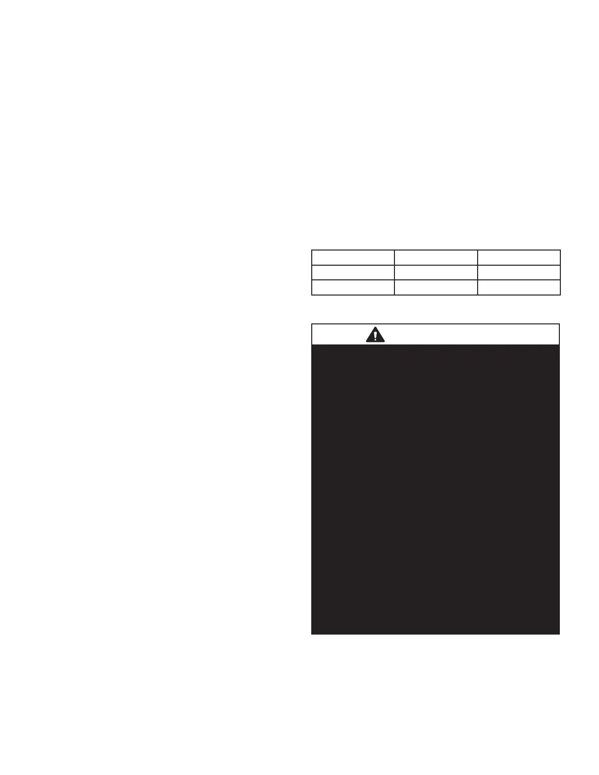
TABLE 5
MINIMUM AND MAXIMUM PULLEY ADJUSTMENT
Belt Min Turns Open Max Turns Open
A Section No Min 5
B Section 1*
6
*No minimum number of turns open when B belt is used
on pulleys 6” O.D. or larger.
IMPORTANT
Three Phase Scroll Compressor Voltage Phasing
Three phase scroll compressors must be phased
sequentially to ensure correct compressor and
blower* rotation and operation. Compressor and
blower are wired in phase at the factory. Power wires
are color-coded as follows: line 1-red, line 2-yellow,
line 3-blue.
1-Observe suction and discharge pressures and
blower* rotation on unit start-up.
2-Suction pressure must drop, discharge pressure
must rise and blower* rotation must match rotation
marking.
rotation is not correct:
3-Disconnect all remote electrical power supplies.
to the line side of S48 disconnect or TB13 terminal
strip. Do not reverse wires at blower contactor.
5-Make sure the connections are tight.
Discharge and suction pressures should operate at
their normal start-up ranges.
*Supply air inverter blower motors should rotate
in the correct direction; verify scroll compressor
rotation separately. Contact technical support if the
blower is rotating incorrectly.
 Loading...


