VIII-FACTORY-INSTALLED Hot Gas Re-Heat
General
Hot Gas Re-Heat units provide a dehumidifying mode of
operation. These units contain a reheat coil adjacent to
and downstream of the evaporator coil. Reheat coil sole-
noid valves, L14 and L30, route hot discharge gas from
the compressor to the reheat coil. Return air pulled across
coil adds heat to supply air.
-
-
refrigerant routing.
L14 and L30 Reheat Coil Solenoid Valves
and refrigerant is routed to the reheat coil.
Reheat Setpoint
Reheat is factory-set to energize when indoor relative hu-
midity rises above 60% (default). The reheat setpoint can
be adjusted by changing Unit Controller Settings - Control
menu. A setting of 100% will operate reheat from an ener-
gy management system digital output. The reheat setpoint
can also be adjusted using an optional Network Control
Panel (NCP).
Reheat will terminate when the indoor relative humidity
falls 3% (57% default) or the digital output de-energizes.
The reheat deadband can be adjusted at Settings - Con-
trol menu.
A91 Humidity Sensor
relative humidity is 80% + 3%, the humidity sensor output
should read 8.00VDC.
Check the sensor output annually for accuracy. Keep the
air intake openings on the sensor clean and free of ob-
structions and debris
.
TABLE 39
Relative Humidity (%RH + 3%) Sensor Output (VDC)
20 2.00
30 3.00
40 4.00
50 5.00
60 6.00
70 7.00
80 8.00
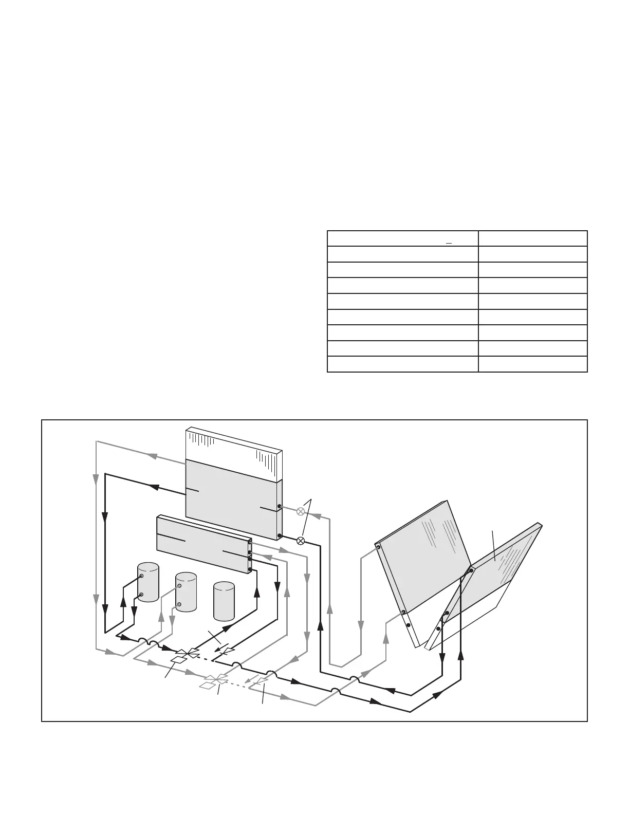
REHEAT MODE REFRIGERANT ROUTING
156, 180H, & 210 UNITS
REHEAT
COIL
CIRCUIT 1
CONDENSER
COIL
CIRCUIT 2
CONDENSER
COIL
STAGE 2
EVAPORATOR
COIL
STAGE 1
EVAPORATOR
COIL
1
2
EXPANSION
VALVES
CHECK
L14
REHEAT
VALVE
L30
REHEAT
VALVE
3
CHECK
VALVE
Note: Two refrigerant circuits are shown; both
circuits operate during reheat.
FIGURE 36
 Loading...


