IX--Staged-Blower
Start-Up
-
er CFM for appropriate unit.
-
vided, set the medium cooling CFM at the high or low
cooling design spec or any CFM between.
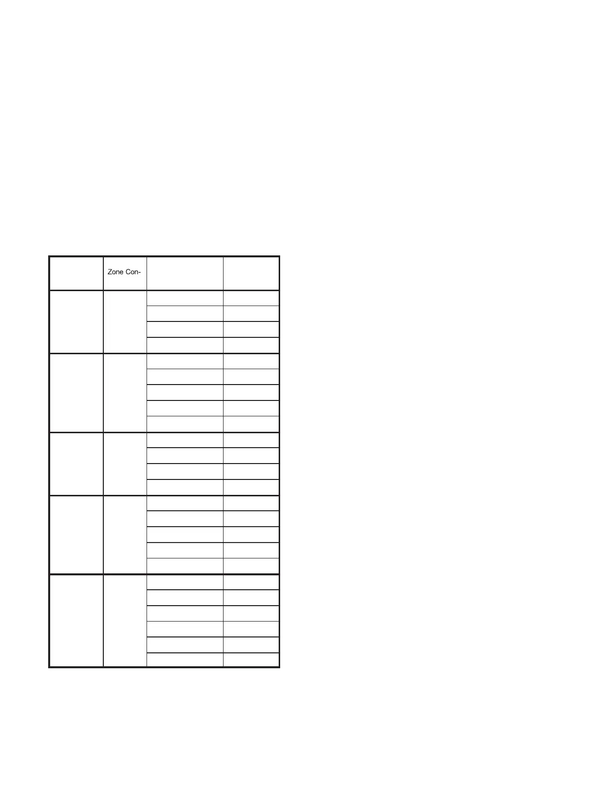
B-Set Maximum CFM
Use table 41 to determine highest blower CFM for appro-
priate unit. Adjust the blower pulley to deliver that amount
of CFM with only the blower operating. See Determining
Unit CFM in the Blower Operation and Adjustment section.
TABLE 41
Unit
T'Stat or
trol Stages
Blower Speed
Design
Specified CFM
156,
180,
210
2
Htg.
Clg. High
Clg. Low
Ventilation
156,
180,
210
3 or 4
Htg.
Clg. High
Clg. Med.
Clg. Low
Ventilation
240, 300 2
Htg.
Clg. High
Clg. Low
Ventilation
240, 300 3
Htg.
Clg. High
Clg. Med.
Clg. Low
Ventilation
240, 300 4
Htg.
Clg. High
Clg. Med. High
Clg. Med. Low
Clg. Low
Ventilation
*Available blower speeds vary by unit and thermostat stages.
M3 Controller
Use the following menu to enter the blower design speci-
is within limitations shown in tables 42 and 43. Refer to the
Unit Controller manual provided with unit.
M2 - Settings / Control / Guided Setup (enter information
as prompted by the Unit Controller if not already done).
M3 - SETUP > TEST & BALANCE > BLOWER >
Advanced Guided Setup (enter information as prompted
by the Unit Controller if not already done).
Setup Equipment / Change Staged-Blower Settings? / Yes
Blower /
Heat CFM
Cooling High CFM
1
Cooling Low CFM
1
Vent CFM
1
The Unit Controller will prompt when more cooling stages
are available depending on the number of compressors
and the control mode.
D-Set Damper Minimum Position
To maintain required minimum ventilation air volumes
when the unit is in the occupied mode, two minimum
damper positions must be set. The Unit Controller will
open the dampers to “Min OCP Blwr Low” when blower
CFM is BELOW a “midpoint” CFM. The Unit Controller will
open the damper to “Min OCP Blwr High” when blower
CFM is at or ABOVE the “midpoint” CFM.
The Unit Controller will calculate the “midpoint” CFM.
Set Minimum Position 1
Use the following menu in the Unit Controller to set “Min
OCP Blwr Low” for the blower CFM below the “midpoint”
CFM. When navigating into this menu, the Unit Controller
will bring on the corresponding blower speed and allow
damper position adjustment.
M2 - Settings / Control / Staged-Blower / Damper / Low
Speed
M3 - SETTINGS > RTU OPTIONS > EDIT PARAMETER
X.X%
Measure the intake air CFM. If the CFM is lower than the
-
troller to increase the damper percent open. If the CFM is
Note - Intake air CFM can also be determined using the
outdoor air temperature, return air temperature and mixed
air temperature. Refer to the economizer or outdoor air
damper installation instructions.
 Loading...


