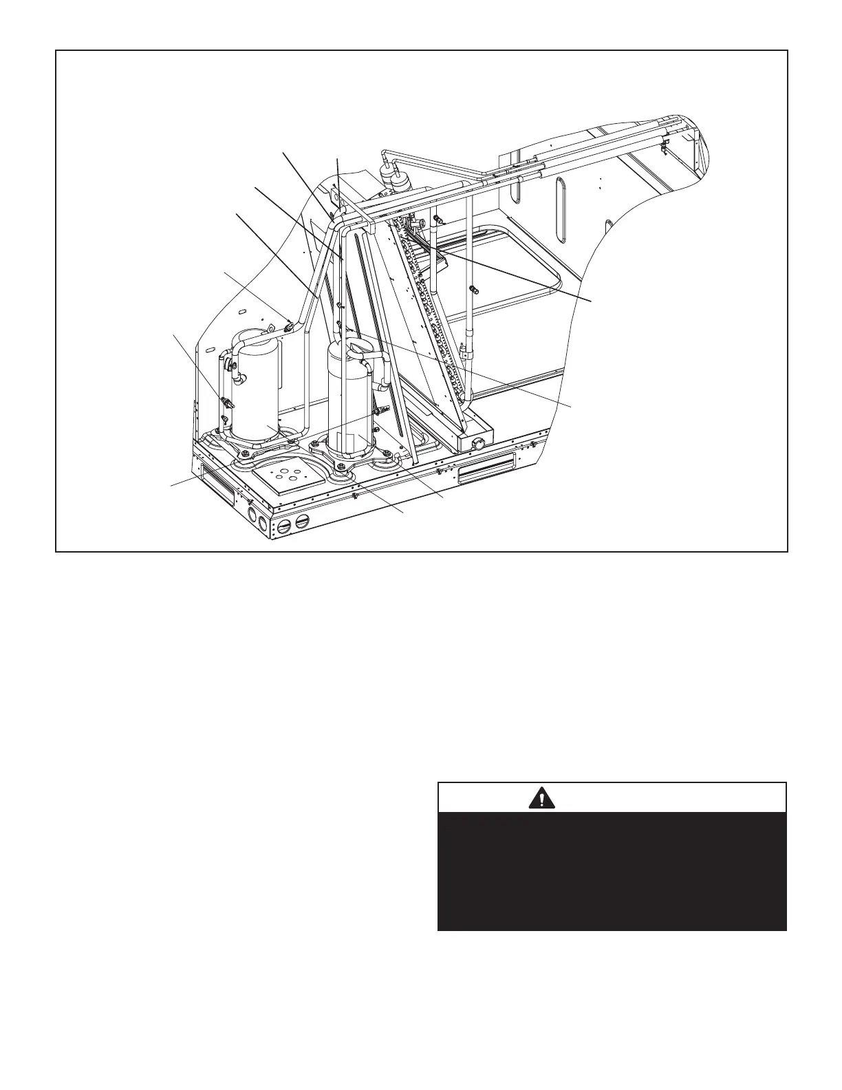
PLUMBING, COMPRESSOR AND REFRIGERANT CIRCUITS DETAIL
Low Pressure Switch
S87
Low Pressure Switch
S88
High Pressure
Switch
S4
High Pressure
Switch
S7
Evaporator Coil
Compressor
B1
Compressor
B2
Discharge Line
Stage 1
Discharge Line
Stage 2
Suction Line
Stage 1
Suction Line
Stage 2
FIGURE 6
B-Cooling Components
ECM direct drive blowers which draw air across the evap-
orator during unit operation.
On all units the evaporators are slab type and are row split.
Each evaporator uses a thermostatic expansion valve as
the primary expansion device.
-
ditional protection is provided by by thermistors for low
ambient control and freezing prevention.
-
stalled economizer.
1-Compressors B1, B2
Units are equipped with two scroll compressors and two
is single stage compressor. Compressor capacity may
compressor is added to reach the total capacity of the unit.
-
ble of contents) or compressor nameplate for compressor
WARNING
Electrical shock hazard. Compressor must be
grounded. Do not operate without protective
coverover terminals. Disconnect power before
removing protective cover. Discharge capacitors
before servicing unit. Failure to follow these
precautions could cause electrical shock resulting
in injury or death.

 Loading...