Page 49
VIII-Direct Drive Supply Air Inverter
If a test and balance contractor has not commissioned the
A-Set Blower Speed
1 -
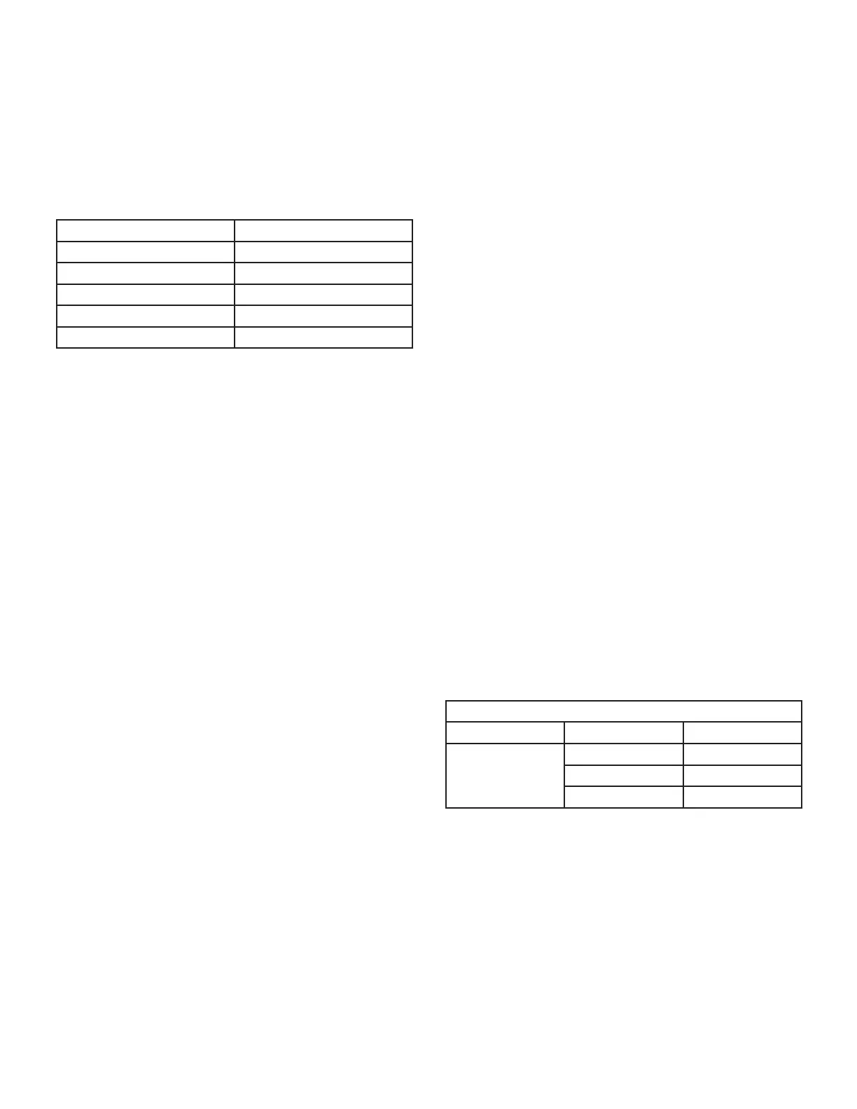
TABLE 16
Blower Speed
Cooling Medium
Cooling Low
Ventilation
2 - Use the following menu to enter the blower design
the Unit Controller manual provided with unit.
3 -
RPM will be displayed.
Note - When units are not equipped with heat, the
Blower Heat speed will not be displayed. Blower
Cooling High will be the rst blower speed to appear.
4 - Measure the static pressure as shown in the Blower
Enter the RPM and repeat the previous step until
6 - Press SAVE followed by MAIN MENU.
Note - Once the CFM settings are saved, the Unit
Controller will set all other blower CFM.
B-Set Damper Minimum Position
To maintain required minimum ventilation air volumes
damper positions must be set. The Unit Controller will
open the dampers to “Min OCP Blwr Low” when blower
Set Minimum Position 1
Use the following menu in the Unit Controller to set “Min
will bring on the corresponding blower speed and allow
damper position adjustment.
-
-
Note - Intake air CFM can also be determined using the
outdoor air temperature, return air temperature and mixed
air temperature. Refer to the economizer or outdoor air
damper installation instructions.
Set Minimum Position 2
Use the same menu in the Unit Controller to set “Min OCP
bring on the corresponding blower speed and allow damp-
er position adjustment.
-
-
Note - Intake air CFM can also be determined using the
outdoor air temperature, return air temperature and mixed
air temperature. Refer to the economizer or outdoor air
damper installation instructions.
TABLE 17
MINIMUM AND MAXIMUM CFM
Unit
Standard
Medium

 Loading...