Page 25
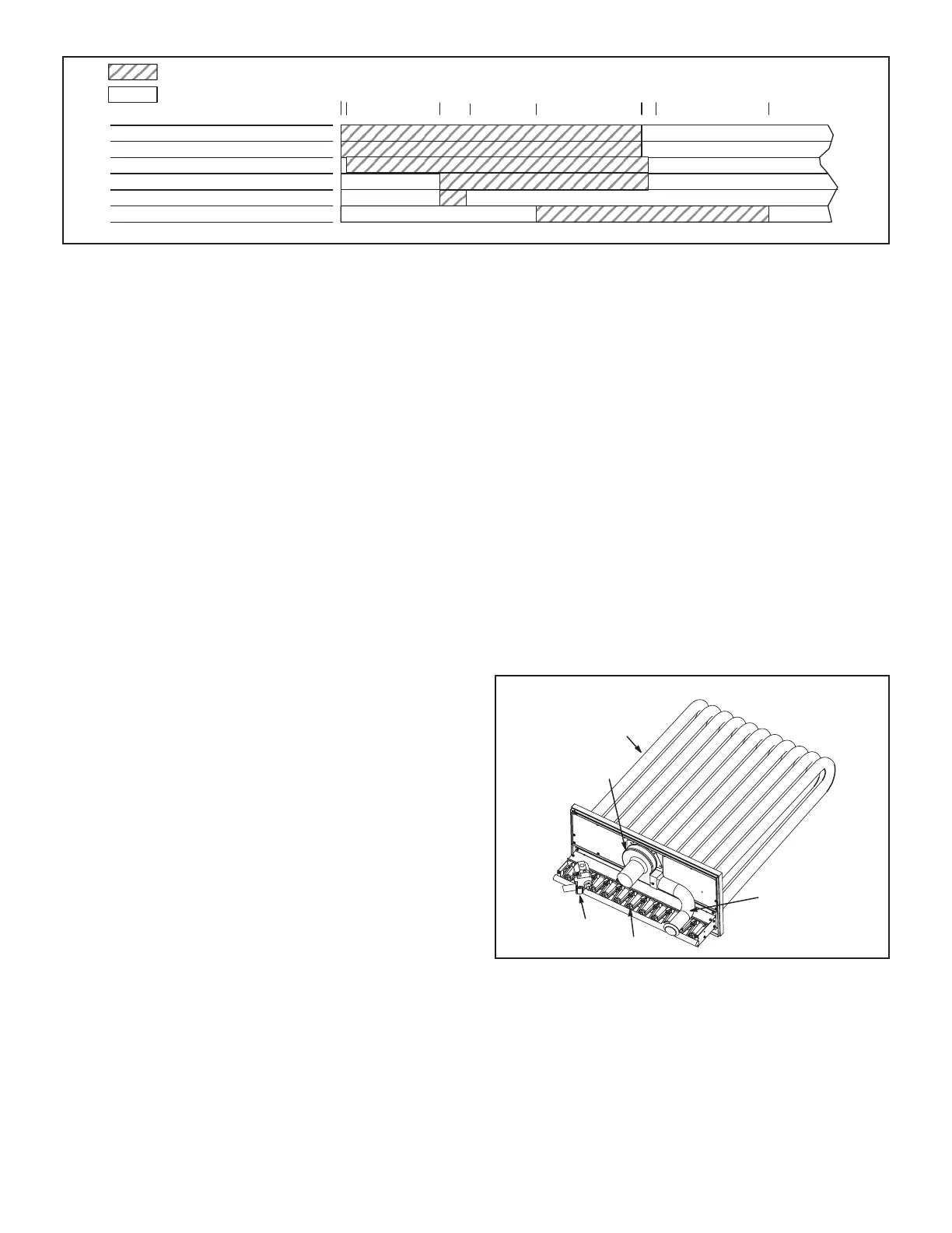
NORMAL IGNITION SEQUENCE - TIMINGS NOMINAL
THERMOSTAT DEMAND
COMBUSTION AIR BLOWER
GAS VALVE
IGNITION SPARK
BLOWER
IGNITION TRIAL
011053030SDNOCES
ON / CLOSED
OFF / OPEN
END OF
DEMAND
1
COMBUSTION AIR PROVE SWITCH
5 570
FIGURE 13
Flame rectication sensing is used on all units. Loss of
ame during a heating cycle is indicated by an absence of
ame signal (0 microamps). If this happens, the control will
immediately restart the ignition sequence and then lock
out if ignition is not gained after the third trial. See System
Service Checks section for ame current measurement.
The control shuts o gas ow immediately in the event of
a power failure. Upon restoration of gas and power, the
control will restart the ignition sequence and continue until
ame is established or system locks out.
On a heating demand, the ignition control is energized by
the A55 Unit Controller. The ignition control then allows
30 to 40 seconds for the combustion air blower to vent
exhaust gases from the burners. When the combustion
air blower is purging the exhaust gases, the combustion
air prove switch is closing proving that the combustion air
blower is operating before allowing the ignition control to
energize. When the combustion air prove switch is closed
and the delay is over, the ignition control activates gas
valve, the spark electrode and the ame sensing elec-
trode. Sparking stops immediately after ame is sensed.
The combustion air blower continues to operate through-
out the heating demand. If the ame fails or if the burners
do not ignite, the ignition control will attempt to ignite the
burners up to two more times. If ignition cannot be ob-
tained after the third attempt, the control will lock out. The
ignition control is not adjustable.
2-Heat Exchanger (Figure 14)
The LGT units use cluster type inshot burners with match-
ing tubular aluminized (stainless steel is an option) steel
heat exchangers and two-stage redundant gas valves.
Units are equipped with one eleven tube/burner for high
heat and one nine tube/burner for medium heat. Burners
use a burner venturi to mix gas and air for proper com-
bustion.
Combustion takes place at each tube entrance. As hot
combustion gases are drawn upward through each tube
by the combustion air blower, exhaust gases are drawn
out the top and fresh air/gas mixture is drawn in at the
bottom. Heat is transferred to the air stream from all sur-
faces of the heat exchanger tubes. The supply air blowers,
controlled by the A55 Unit Controller, force air across all
surfaces of the tubes to extract the heat of combustion.
The shape of the tubes ensures maximum heat exchange
The gas valves accomplish staging by allowing more or
less gas to the burners as called for by heating demand.
3-Gas Heat Exchanger Inserts (Some LGT Units)
Inserts are installed on standard (130,000Btuh) heat ex-
changers in tubes one and three. Medium and high heat
exchangers do not require inserts. See gure 15. Inserts
are used to maintain even temperature distribution through
the heat exchanger. Temperature distribution can vary
depending on supply air ow, number of heat exchanger
tubes and the blower deck opening.
HEAT EXCHANGER ASSEMBLY
BURNER
COMBUSTION
AIR INDUCER
VENT
CONNECTOR
GAS VALVE
HEAT
EXCHANGER
TUBE
FIGURE 14
 Loading...
