5-Proper Gas Flow
input from unit rating plate or the gas heating capacity in
the Btuh per cubic foot of available gas. Result is the num-
NOTE - To obtain accurate reading, shut o all other gas
appliances connected to meter.
6-Inshot Burner
Burners are factory set for maximum air and cannot be
adjusted. Always operate unit with access panel in place.
A peep hole is furnished in the heating access panel for
some clear streaks. L.P. gas should burn mostly blue with
some clear yellow streaks.
1 -
2 - Remove screws holding the burner support cap.
3 -
and can be removed as one.
4 - Clean and reassemble (reverse steps 1-3).
Be sure to secure all wires and check plumbing.
6 -
attached to unit and operate unit in heating mode.
yellow streaks.
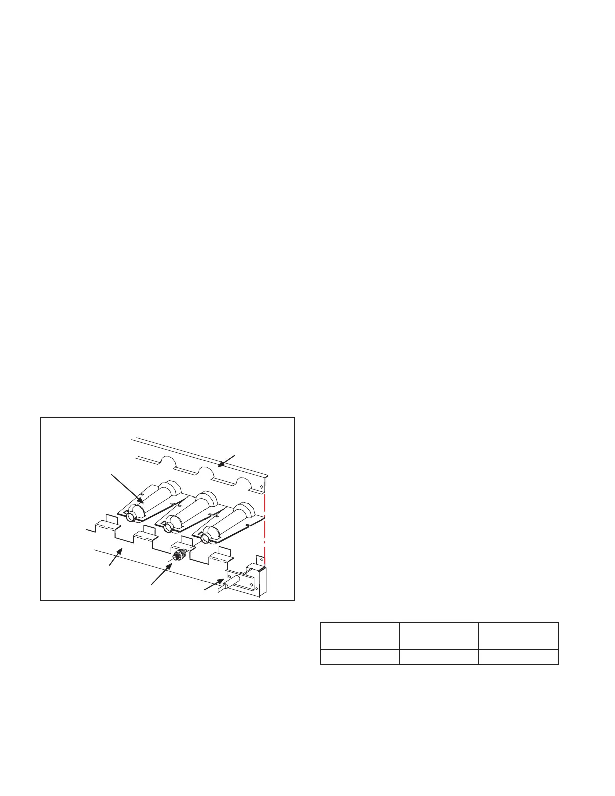
TYPICAL GAS BURNER ASSEMBLY
BURNERS
(Typical)
ORIFICE
BURNER
SUPPORT
BURNER
SUPPORT CAP
FIGURE 26
7-Spark Electrode Gap
The spark electrode assembly can be removed for inspec-
tion by removing two screws securing the electrode as-
sembly and sliding it out of unit.
and the spark gap set correctly.Spark gap may be checked
with appropriately sized twist drills or feeler gauges.
Disconnect power to the unit and remove electrode as-
8-Heat Exchanger
1 -
2 - Remove access panel(s) and unit center mullion.
3 -
4 -
careful attention to the order in which gaskets and
Support heat exchanger (to prevent it from falling
6 - Remove screws supporting heat exchanger.
sure to secure all wires and check plumbing and
burner plate for airtight seal. Screws must be
9-Flame Sensing
the ignition control through the sensor electrode during
unit operation.
complete a safety circuit. The electrodes should be locat-
-
NOTE-Electrodes are not eld adjustable. Any alterations
to the electrode may create a hazardous condition that
can cause property or personal injury.
1 - Disconnect power to unit.
2 - Remove lead from sensing electrode and install
sensing electrode and the sensing lead.
3 - Reconnect power and adjust thermostat for heating
demand.
4 -
table 12. Do not bend electrodes.
Disconnect power to unit before disconnecting
meter. Make sure sensor wire is securely
reconnected before reconnecting power to unit.
TABLE 12
Manufacturer
Nominal Signal
Microamps
Drop Out
NOTE-If the meter scale reads 0, the leads are reversed.
Disconnect power and reconnect leads for proper polarity.

 Loading...