Page 2
LHT/LDT156, 180, 240
WARNING
To prevent serious injury or death:
1- Lock-out/tag-out before performing maintenance.
2- If system power is required (e.g., smoke detector mainte
nance), disable power to blower, remove fan belt where
applicable, and ensure all controllers and thermostats are
set to the “OFF” position before
performing maintenance.
3- Always keep hands, hair, clothing, jewelry, tools, etc.,
away from moving part
s.
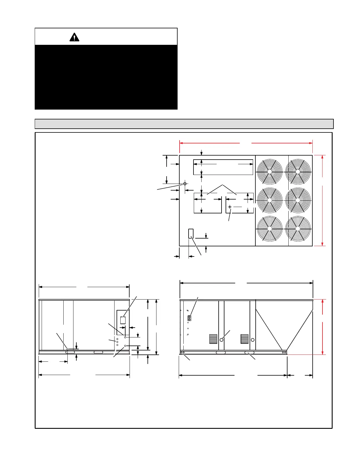
LHT/LDT DIMENSIONS
4−1/4 (108)
12−3/8
(314)
(314)
12−3/8
4
(102)
BOTTOM SUPPL
Y
AIR OPENINGS
BOTTOM RETURN
AIR OPENING
28
(711)
28
(711)
20 (508)
15 (381)
60−1/2 (1537)
AA
BB
CC
DD
CENTER OF
GRAVITY
TOP VIEW
4−1/2
(114)
20 (508)
BOTTOM POWER ENTRY
5 X 8 inches (127 X 203 mm)
4
(102)
END VIEW
90−1/8
(2289)
28−3/4
(730)
5−3/8
(137)
3−1/4
(83)
54−1/4
(1378)
51
(1295)
91−1/8 (2315)
BASE
8−1/4
(210)
10−1/4
(260)
4
(102)
OPTIONAL
DISCONNECT
(Factory Installed)
CONDENSA
TE
DRAIN
FLUE
OUT LET
SIDE VIEW
FORKLIFT SLOTS
(Front and Left Side Only)
132−5/8
(3369)
LIFTINGHOLES
(For Rigging
Front and Back)
25−3/8
(645)
107−3/4
(2737)
BASE
OPTIONAL
115 VOLT OUTLET
(Factory Installed Inside Unit)
FLUE
OUT LET
ALTERNATE (THRU THE BASE)
CONDENSATE DRAIN LOCATION
1−5/8 in. (41 mm) Diameter
18 (457)
28−3/8
(721)
5−5/8 (143)
91−1/8
(2315)
133−1/8
(3381)
54−1/4
(1378)
ELECTRICAL
INLETS
GAS SUPPLY INLET
SIDE
GAS SUPPLY OUTLET
(For Bottom
Gas Supply Only)

 Loading...


