Page 22
LHT/LDT156, 180, 240
11- The ignition sequence will start.
12- If the appliance does not light the first time (gas line
not fully purged), it will attempt up to two more
ignitions before locking out.
13- If lockout occurs, repeat steps 1 through 10.
14- If the appliance will not operate, follow the
instructions “Turning Off Gas to Appliance” and call
your service technician or gas supplier.
Turning Off Gas to Unit
1- If using an electromechanical thermostat, set to the
lowest setting.
2- Before performing any service, turn off all electrical
power to the appliance.
3- Open or remove the heat section access panel.
4- Turn gas valve switch to OFF.
5- Close or replace the heat section access panel.
WARNING
Danger of explosion. Can cause injury or
death. Do not attempt to light manually.
Unit has a direct spark ignition system.
Heating Operation and Adjustments
(Gas Units)
A-Heating Sequence of Operation
1- On a heating demand the combustion air inducer
starts immediately.
2- Combustion air pressure switch proves inducer
operation. After a 30-second pre-purge, power is
allowed to ignition control. Switch is factory set and
requires no adjustment.
3- Spark ignitor energizes and gas valve solenoid
opens.
4- Spark ignites gas, ignition sensor proves the flame
and combustion continues.
5- If flame is not detected after first ignition trial, ignition
control will repeat steps 3 and 4 two more times
before locking out the gas valve.
6- For troubleshooting purposes, an ignition attempt
after lock out may be re-established manually. Move
thermostat to “OFF” and return thermostat switch to
“HEAT” position.
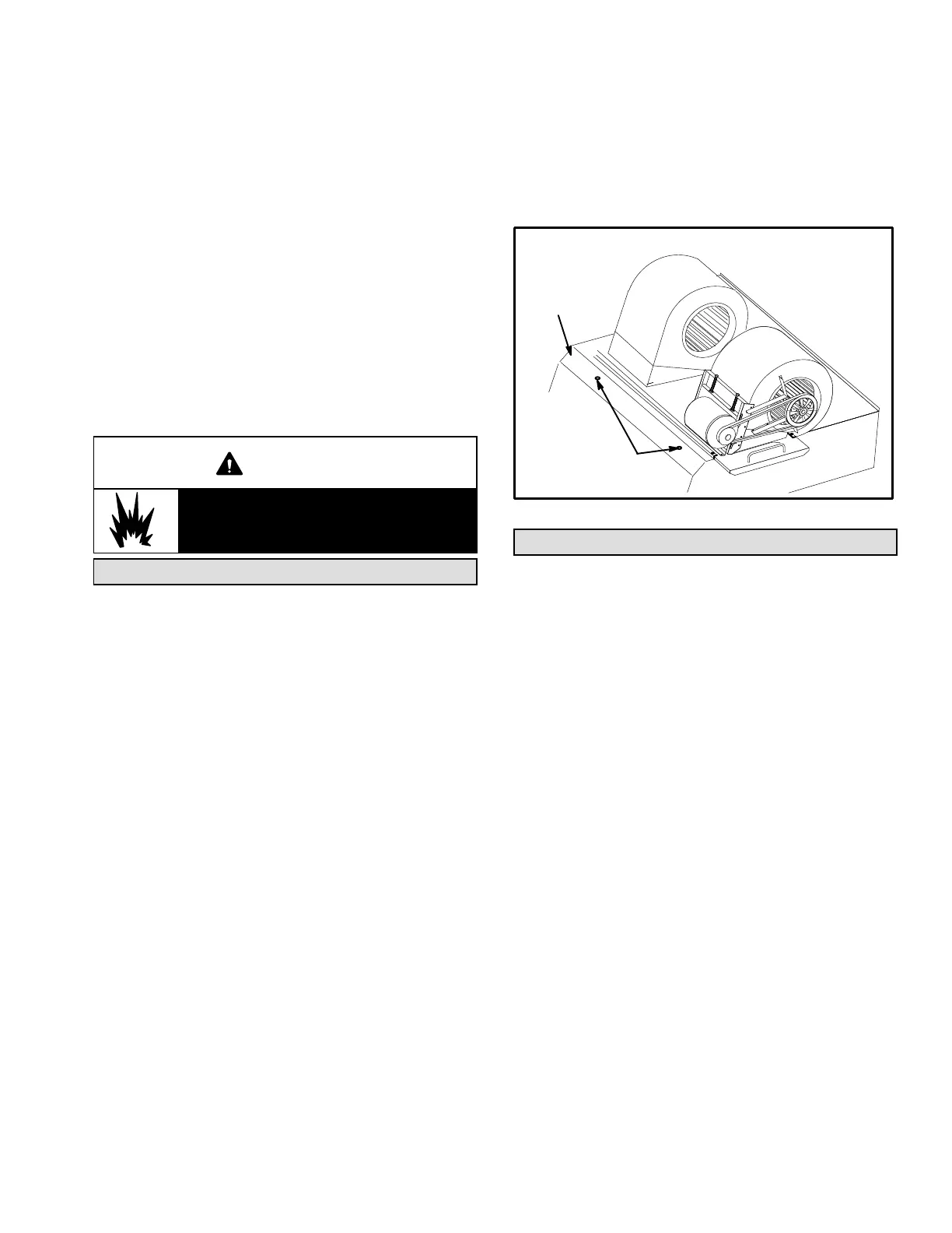
B-Limit Controls
Limit controls are factory-set and are not adjustable. Two
limits are located on the drip shield in the blower
compartment. See figure 18.
C-Heating Adjustment
Main burners are factory-set and do not require adjustment.
The following manifold pressures are listed on the gas valve.
Natural Gas Units - Low Fire - 1.6” w.c.
(not adjustable)
Natural Gas Units - High Fire - 3.7” w.c.
LP Gas Units - Low Fire - 5.5” w.c.
(not adjustable)
LP Gas Units - High Fire - 10.5” w.c.
LIMIT LOCATION
FIGURE 18
LIMITS
DRIP
SHIELD
Heating Start-Up (LHT)
Note - L1 & L2 reversing valves are de-energized with a
heating demand. The heat pump will heat only, not cool.
1- Set thermostat or temperature control device to
initiate a first-stage heating demand.
2- A first-stage heating demand (W1) will energize
compressors 1 and 2, the outdoor fans, and blower.
Note - W1 will also energize optional factory- or
field-installed electric heat during defrost to maintain
discharge air temperature.
3- A second-stage heating demand (W2) will energize
optional electric heat.

 Loading...


