16
DC-FAN
CN 414
3
AMBIENT TEMP. SENSOR
DISCHARGE TEMP. SENS OR
CN 17
.
Y/G
OUTDOOR
MAIN
PCB
BLUE
BROWN 1
3
2
L1
L2
RED
BLUE L2
1
Y/G
CN 3
Y/G
COMPRESSOR
Y/G
U
V
W
BLUE
RED
BLACK
L1
L2
S
CN 6
CN 7
CN 8 CN 2
CN 21
W
V
U
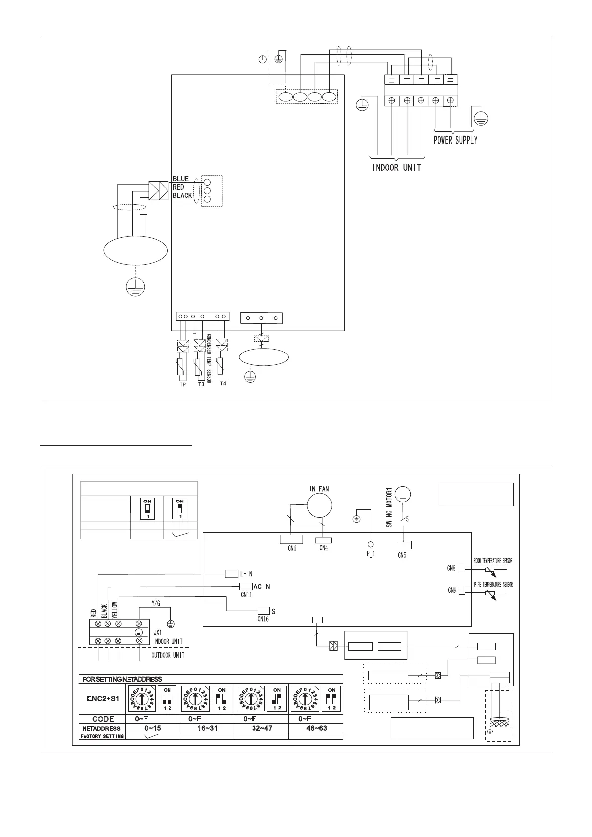
Figure 31. 18K and 24K 208/230VAC Outdoor Unit Wiring Diagram
Wiring Diagrams (Indoor Units)
M
M
~
3
3
1
2
3
MAIN CONTROL BOARD
0
8
4
1
2
3
5
6
7
C
9
A
B
D
E
F
1
2
ON
0
8
4
1
2
3
5
6
7
C
9
A
B
D
E
F
1
2
ON
0
8
4
1
2
3
5
6
7
C
9
A
B
D
E
F
1
2
ON
0
8
4
1
2
3
5
6
7
C
9
A
B
D
E
F
1
2
ON
ENC2+S1
0~F 0~F 0~F 0~F
NETADDRESS
CODE
0~15
16~31 32~47 48~63
FOR SETTING NETADDRESS
CN10A
DI SP LA Y BOARD
8
Wired Controller
OPTIONAL
ADAPTER BOARD
CN 3 (C N3 01
)
CN 50 1
CN 40 3
X Y E
To LVM
Comm.Bus
YELLOW
BROWN
RED
5
5
Programmable
Wired Controller
OPTIONAL
4
Note: The programmable wired
controller and LVM use the same
port CN403.
CN 2 (C N2 01
)
CN 40 2
NOTE: COMPONENT IN
DASH LINE IS OPTIONAL
OR FIELD WIRING
S5
FOR REMOTE ON/OF
FACTORY SETTING
MODE
REMOTE ON/OFF OFFREMOTE ON/OFF ON
(T1)
(T2)
Figure 32. 09K and 12K Indoor Unit Wiring Diagram (115 and 208/230VAC)
 Loading...