9
4.3. TS02-S-INV
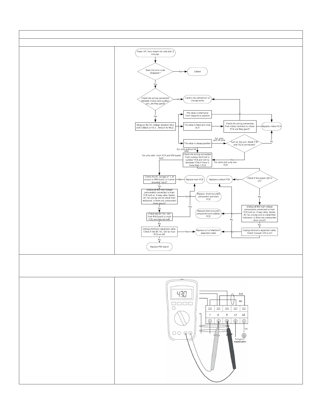
Description: Indoor unit cannot communicate with the outdoor unit.
Possible Affected Components: Indoor PCB, Outdoor PCB, IPM PCB or short-circuited component.
Troubleshooting and Repair:
NOTE: On various models the outdoor PCB can not be removed separately. In this situation the entire outdoor electric
control box should be replaced.
Remarks:
• Use a multimeter to test the DC
voltage between two terminals
(2 and 3).
• When the system is normally
running, the voltage should
alternate between -25V to 25V).
• If the outdoor unit has
malfunction, the voltage will
move alternately with positive
values.
• If the indoor unit has
malfunction, the voltage will
between a certain value.
 Loading...