EasyManua.ls Logo

Lennox Merit 10HPB Series

Lennox Merit 10HPB Series
18 pages
To Next Page IconTo Next Page
Loading...
Page 1
504,828M
*P504828M*
06/04
*2P0604*
2003 Lennox Industries Inc.
Dallas, Texas, USA
®
10HPB Outdoor Units
Lennox Merit
®
Series 10HPB outdoor units are approved
and warranted only for installation with specially matched
indoor coils, line sets, and refrigerant control systems as
designated by Lennox. Refer to Lennox Engineering
Handbook for expansion valve kits which must be ordered
separately.
Shipping and Packing List
1 − Assembled 10HPB outdoor unit
1 − Coupling (18, 24 and 30)
Check unit for shipping damage. Consult last carrier imme-
diately if damage is found.
WARNING
Improper installation, adjustment, alteration, service
or maintenance can cause property damage, person-
al injury or loss of life. Installation and service must
be performed by a qualified installer or service
agency.
IMPORTANT
The Clean Air Act of 1990 bans the intentional vent-
ing of refrigerant (CFC’s and HCFC’s) as of July 1,
1992. Approved methods of recovery, recycling or
reclaiming must be followed. Fines and/or incarcera-
tion may be levied for noncompliance.
INSTALLATION
INSTRUCTIONS
10HPB Series Units
HEAT PUMP UNITS
1−1/2 through 5 tons
504,828M
06/04
Supersedes 02/04
Table of Contents
10HPB Outdoor Units 1. . . . . . . . . . . . . . . . . . . . . . . . . . .
Shipping & Packing List 1. . . . . . . . . . . . . . . . . . . . . . . . .
General Information 1. . . . . . . . . . . . . . . . . . . . . . . . . . . .
Unit Dimensions 2. . . . . . . . . . . . . . . . . . . . . . . . . . . . . . .
Setting the Unit 3. . . . . . . . . . . . . . . . . . . . . . . . . . . . . . . .
Electrical 4. . . . . . . . . . . . . . . . . . . . . . . . . . . . . . . . . . . . . .
Refrigerant Piping 6. . . . . . . . . . . . . . . . . . . . . . . . . . . . . .
Refrigerant Metering Device 10. . . . . . . . . . . . . . . . . . . .
Manifold Gauge Set 10. . . . . . . . . . . . . . . . . . . . . . . . . . .
Service Valves 11. . . . . . . . . . . . . . . . . . . . . . . . . . . . . . . .
Leak Testing 12. . . . . . . . . . . . . . . . . . . . . . . . . . . . . . . . . .
Evacuation 13. . . . . . . . . . . . . . . . . . . . . . . . . . . . . . . . . . .
Start−Up 13. . . . . . . . . . . . . . . . . . . . . . . . . . . . . . . . . . . . . .
Charging 14. . . . . . . . . . . . . . . . . . . . . . . . . . . . . . . . . . . . .
System Operation 16. . . . . . . . . . . . . . . . . . . . . . . . . . . . .
Defrost System 16. . . . . . . . . . . . . . . . . . . . . . . . . . . . . . .
Maintenance 18. . . . . . . . . . . . . . . . . . . . . . . . . . . . . . . . . .
Optional Accessories 18. . . . . . . . . . . . . . . . . . . . . . . . . .
Start−Up and Performance Check List 18. . . . . . . . . . . .
RETAIN THESE INSTRUCTIONS
FOR FUTURE REFERENCE
General Information
These instructions are intended as a general guide and do
not supersede national or local codes in any way. Authori-
ties having jurisdiction should be consulted before instal-
lation.
WARNING
This product and/or the indoor unit it is matched with
may contain fiberglass wool.
Disturbing the insulation during installation, mainte-
nance, or repair will expose you to fiberglass wool
dust. Breathing this may cause lung cancer. (Fiber-
glass wool is known to the State of California to
cause cancer.)
Fiberglass wool may also cause respiratory, skin,
and eye irritation.
To reduce exposure to this substance or for further
information, consult material safety data sheets
available from address shown below, or contact your
supervisor.
Lennox Industries Inc.
P.O. Box 799900
Dallas, TX 75379−9900
Litho U.S.A.
Question and Answer IconNeed help?

Do you have a question about the Lennox Merit 10HPB Series and is the answer not in the manual?

Lennox Merit 10HPB Series Specifications

General IconGeneral
BrandLennox
ModelMerit 10HPB Series
CategoryHeat Pump
LanguageEnglish

Summary

10 HPB Outdoor Units

Shipping and Packing List

Instructions for unpacking and verifying unit contents.

General Information

Overview of installation guidelines and important notices.

Setting the Unit

Installation Clearances

Required spacing around the unit for airflow and service.

Slab Mounting

Guidelines for installing the unit on a ground-level slab.

Roof Mounting

Recommendations for mounting the unit on a roof surface.

Electrical Installation

Electrical Connections and Wiring

Procedures for power supply, grounding, and low-voltage wiring.

Refrigerant Piping

Installing Refrigerant Lines

Guidance on connecting and routing the liquid and vapor lines.

Line Set Isolation

Techniques to prevent vibration and noise transmission.

Vertical Runs of Refrigerant Piping

Refrigerant Line Contact Rules

Critical instructions to prevent refrigerant lines from touching structures.

Horizontal Runs of Refrigerant Piping

Hanging Line Sets

Methods for supporting horizontal refrigerant lines from joists or rafters.

Transitioning Refrigerant Piping

Vertical to Horizontal Runs

Procedures for connecting vertical and horizontal refrigerant line sections.

Outdoor Unit Placement

Optimal Unit Location

Recommendations for positioning the outdoor unit away from windows.

Brazing Connection Procedure

Brazing Steps

Step-by-step guide for brazing refrigerant line connections.

Refrigerant Metering Device

Metering Device Installation

Instructions for installing the expansion valve or fixed orifice.

Manifold Gauge Set

Gauge Set Usage

Guidelines for using a manifold gauge set for system checks.

Service Valves

Accessing Schrader Ports

How to connect gauges to the service valve ports.

Operating Line Service Valves

Procedures for opening and closing liquid/vapor line service valves.

Ball-Type Vapor Line Service Valve

Description and operation of the ball-type service valve.

Leak Testing

Leak Detection Methods

Techniques for identifying refrigerant leaks in the system.

Evacuation

System Evacuation Procedure

Steps to remove non-condensables and moisture from the system.

Start-Up Procedures

Crankcase Heater Pre-Start

Requirement to energize the crankcase heater before starting the unit.

Charging the System

Weighing Refrigerant Charge

Method for charging refrigerant by weight for TXV systems.

Subcooling Method Charging

Procedure for charging based on liquid line subcooling.

Charging with Normal Operating Pressures

Approach Method Charging

Method for charging based on ambient and liquid line temperatures.

System Operation

Filter Drier

Information on the unit's filter drier component.

Crankcase Heater

Description of the crankcase heater function.

Emergency Heat Function

Emergency Heat Operation

How the emergency heat feature works and when to use it.

Defrost System

Defrost Thermostat

Role of the defrost thermostat in initiating defrost cycle.

Defrost Control

Functionality of the defrost control board.

Defrost Control Timing

Settings for defrost cycle initiation intervals.

Pressure Switch Circuit

High Pressure Switch Operation

How the optional high pressure switch affects unit operation.

Diagnostic LEDs

Defrost Control Board LEDs

Interpreting LED flash patterns for diagnostics.

Maintenance Procedures

Outdoor Unit Maintenance

Steps for cleaning and inspecting the outdoor unit.

Indoor Coil Maintenance

Instructions for cleaning the indoor coil.

Start-Up and Performance Checklist

Optional Accessories

List of available optional accessories for the unit.
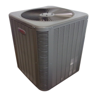
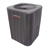
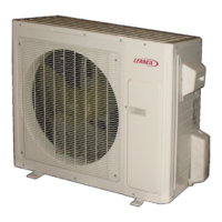
Related product manuals