11/09 506377−01
*2P1109* *P506377-01*
Page 1
2009 Lennox Industries Inc.
Dallas, Texas, USA
RETAIN THESE INSTRUCTIONS
FOR FUTURE REFERENCE
WARNING
Improper installation, adjustment, alteration, service or
maintenance can cause personal injury, loss of life, or
damage to property.
Installation and service must be performed by a licensed
professional installer (or equivalent) or a service agency.
IMPORTANT
The Clean Air Act of 1990 bans the intentional venting of
refrigerant (CFCs, HCFCs and HFCs) as of July 1, 1992.
Approved methods of recovery, recycling or reclaiming
must be followed. Fines and/or incarceration may be
levied for noncompliance.
IMPORTANT
This unit must be matched with an indoor coil as
specified in Lennox Engineering Handbook. Coils
previously charged with HCFC−22 must be flushed.
WARNING
Electric Shock Hazard. Can cause injury
or death. Unit must be grounded in
accordance with national and local
codes.
Line voltage is present at all components
when unit is not in operation on units with
single-pole contactors. Disconnect all
remote electric power supplies before
opening access panel. Unit may have
multiple power supplies.
INSTALLATION
INSTRUCTIONS
Merit
®
Series 14HPX Units
HEAT PUMP UNITS
506377−01
11/09
Supersedes 505,243M
TABLE OF CONTENTS
Shipping and Packing List 1. . . . . . . . . . . . . . . . . . . . . . . .
General 1. . . . . . . . . . . . . . . . . . . . . . . . . . . . . . . . . . . . . . . .
Unit Dimensions 2. . . . . . . . . . . . . . . . . . . . . . . . . . . . . . . . .
Typical Unit Parts Arrangement 2. . . . . . . . . . . . . . . . . . .
Model Number Identification 3. . . . . . . . . . . . . . . . . . . . . .
General Information 3. . . . . . . . . . . . . . . . . . . . . . . . . . . . .
Operating Gauge Set and Service Valves 3. . . . . . . . . . .
Recovering Refrigerant from Existing System 5. . . . . . .
New Outdoor Unit Placement 6. . . . . . . . . . . . . . . . . . . . .
New or Replacement Line Set 6. . . . . . . . . . . . . . . . . . . . .
Metering Devices and Flushing the System 10. . . . . . . .
Testing for Leaks 11. . . . . . . . . . . . . . . . . . . . . . . . . . . . . . .
Evacuating the System 12. . . . . . . . . . . . . . . . . . . . . . . . . .
Electrical Connections 13. . . . . . . . . . . . . . . . . . . . . . . . . .
Servicing Unit Delivered Void of Charge 16. . . . . . . . . . .
Start−Up 16. . . . . . . . . . . . . . . . . . . . . . . . . . . . . . . . . . . . . . .
System Refrigerant 16. . . . . . . . . . . . . . . . . . . . . . . . . . . . .
Removing and Installing Louvers 21. . . . . . . . . . . . . . . . .
System Operation 22. . . . . . . . . . . . . . . . . . . . . . . . . . . . . .
Defrost System 22. . . . . . . . . . . . . . . . . . . . . . . . . . . . . . . .
Maintenance 26. . . . . . . . . . . . . . . . . . . . . . . . . . . . . . . . . . .
Start−Up and Performance Checklist 28. . . . . . . . . . . . . .
Shipping and Packing List
Check the unit components for shipping damage. If you
find any damage, immediately contact the last carrier.
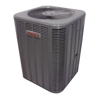
1 − Assembled 14HPX outdoor unit
General
The Merit
®
14HPX model is designed for use with
HFC−410A refrigerant only. This unit must be installed with
an approved indoor air handler or coil. See the Lennox
14HPX Engineering Handbook for approved indoor
component matchups.
IMPORTANT
This model is designed for use in expansion valve
systems only. An indoor expansion valve approved for
use with HFC−410A refrigerant must be ordered
separately, and installed prior to operating the system.
Litho U.S.A.