EasyManua.ls Logo

Lennox 14HPX-036-230-18 User Manual

Lennox 14HPX-036-230-18
52 pages
To Next Page IconTo Next Page
Page #1 background imageLoading...
Page #1 background image
Page 1
Corp. 0719-L5
14HPX
Service Literature
Revised April, 2017
INSTALLATION AND SERVICE
PROCEDURE
LOUVERED
NON-LOUVERED
WARNING
Improper installation, adjustment, alteration, service or
maintenance can cause personal injury, loss of life, or
damage to property.
Installation and service must be performed by a licensed
professional installer (or equivalent) or a service agency.
IMPORTANT
This unit must be matched with an indoor coil as
specified in Lennox Product Specification bulletin. Coils
previously charged with HCFC-22 must be flushed.
WARNING
Electric Shock Hazard. Can cause injury or
death. Unit must be grounded in
accordance with national and local codes.
Line voltage is present at all components
when unit is not in operation on units with
single‐pole contactors. Disconnect all
remote electric power supplies before
opening access panel. Unit may have
multiple power supplies.
TABLE OF CONTENTS
Model Number Identification 2......................
Typical Serial Number Identification 2..............
Specifications 2.................................
Electrical Data 4................................
Unit Dimensions 7.................................
Typical Unit Parts Arrangement 8...................
General Information 9.............................
Operating Gauge Set and Service Valves 9...........
Unit Placement 12.................................
Removing and Installing Louvers 13.................
New or Replacement Line Set 15....................
Brazing Connections 17...........................
Flushing Line Set and Indoor Coil 20................
Installing Indoor Metering Device 21................
Leak Test Line Set and Indoor Coil 22...............
Evacuating Line Set and Indoor Coil 23.............
Electrical Connections 24..........................
System Operation (14HPX-XXX-230-01 through -016)26
Defrost System (14HPX-XXX-230-01 through -016) 26.
System Operation (14HPX-XXX-230-017) 31.........
Defrost System (14HPX-XXX-230-017) 31............
Maintenance 32...................................
Start-Up and Performance Checklist 35..............
Sequence of Operations 36.........................
Servicing Unit Void of Charge 40....................
Start-Up 40.......................................
System Refrigerant 40.............................
The Merit
®
14HPX model is designed for use with
HFC-410A refrigerant only. This unit must be installed with
an approved indoor air handler or coil. See the Lennox
14HPX Product Specification bulletin (EHB) for approved
indoor component matchups.
This outdoor unit is designed for use in systems that use the
following refrigerant metering device:
Check thermal expansion valve (CTXV)
IMPORTANT
The Clean Air Act of 1990 bans the intentional venting of
refrigerant (CFCs, HCFCs and HFCs) as of July 1, 1992.
Approved methods of recovery, recycling or reclaiming
must be followed. Fines and/or incarceration may be
levied for noncompliance.
Question and Answer IconNeed help?

Do you have a question about the Lennox 14HPX-036-230-18 and is the answer not in the manual?

Lennox 14HPX-036-230-18 Specifications

General IconGeneral
TypeHeat Pump
Cooling Capacity (BTU/h)36000
Heating Capacity (BTU/h)36000
SEER14
HSPF8.2
Phase1
RefrigerantR-410A
Sound Level (dBA)76

Summary

Specifications and Identification

Specifications

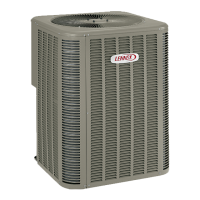
Provides technical specifications for various unit models.

Electrical Data

Electrical Data

Details electrical requirements, ratings, and circuit protection for unit models.

Unit Placement and Mounting

Unit Placement

Details requirements for unit placement and mandatory installation clearances.

Refrigerant Line Set Management

New or Replacement Line Set

Information on installing or replacing existing refrigerant line sets.

Line Set Installation Details

LINE SET INSTALLATION

Illustrates examples of proper refrigerant line set installation techniques.

Brazing Connections

Brazing Connections

Provides procedures and safety warnings for brazing line set connections.

Flushing Line Set and Indoor Coil

FLUSHING LINE SET

Instructions for flushing the line set and indoor unit coil.

Indoor Metering Device Installation

INDOOR EXPANSION VALVE INSTALLATION

Steps for installing the indoor expansion valve unit.

Leak Testing Line Set and Indoor Coil

TEST FOR LEAKS

Procedure for testing line set and indoor unit connections for leaks.

Evacuating Line Set and Indoor Coil

CONNECT GAUGE SET

Instructions for connecting the gauge set for evacuation.

EVACUATE THE SYSTEM

Procedure for evacuating the line set and indoor unit to a specific vacuum level.

Electrical Connections and Thermostat

Electrical

Details electrical wiring requirements and codes for installation.

Wiring and Control Connections

ROUTING HIGH VOLTAGE/ GROUND AND CONTROL WIRING

Instructions for routing high voltage, ground, and control wiring.

System Operation and Defrost (Models -01 to -012)

System Operation (14HPX-XXX-230-01 through -012)

Describes system operation for specific models including component functions.

DEFROST SYSTEM DESCRIPTION

Explains the defrost system's purpose and operation.

Defrost System Sensors

DEFROST SYSTEM SENSORS

Describes the function and resistance values of defrost system sensors.

Defrost Control Operation Modes

DEFROST MODE

Provides a detailed description of the defrost system operation.

DETAILED DEFROST SYSTEM OPERATION

Explains the conditions for initiating and terminating defrost cycles.

Test Mode Operation

TEST MODE OPERATION

Explains how to use test mode for troubleshooting and cycling unit functions.

Defrost Board Diagnostics

DEFROST BOARD DIAGNOSTICS

Details diagnostic LED indicators and their corresponding conditions.

FAULT & LOCKOUT CODES

Explains fault codes, lockout conditions, and their causes.

System Operation and Defrost (Model -017)

Control Features and Maintenance

Start-Up and Performance Checklist

Start-Up and Performance Checklist

A checklist for performing unit start-up and verifying performance.

Sequence of Operations and Diagrams

Operating Sequences and Procedures

Servicing Units Void of Charge

Procedure for servicing units that are void of refrigerant.

Start-Up

Provides essential steps and precautions for unit start-up.

System Refrigerant

Outlines procedures for testing, charging, and adjusting system refrigerant.

Gauge Set Connections

Refrigerant and Airflow Adjustments

ADDING OR REMOVING REFRIGERANT

Details procedures for adding or removing HFC-410A refrigerant.

Refrigerant Charging Methods

WEIGH IN METHOD

Procedure for calculating and adding the initial refrigerant charge by weight.

SUBCOOLING METHOD

Method for verifying refrigerant charge using subcooling measurements.

Related product manuals