Do you have a question about the Lennox 13HPX Series and is the answer not in the manual?
Essential precautions to protect electronic components from electrostatic discharge during installation and service.
Warning regarding the safe handling and responsible use of refrigerant, emphasizing potential personal injury or death.
Explanation of the model number structure and its components for the 13HPX series units.
Details the control box, 24V terminal strip, and wiring connections for the 13HPX units.
Describes the single-pole contactor used to energize the compressor in the 13HPX series.
Explains the dual capacitor used for both the fan motor and compressor in 13HPX units.
Details the defrost thermostat's location and its role in initiating and terminating defrost cycles.
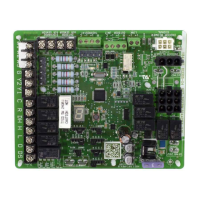
Explains the defrost control board's functions, including timing, diagnostic LEDs, and pressure switch circuits.
Covers the compressor delay function and the test mode for defrost troubleshooting.
Describes the diagnostic LEDs on the defrost control board and their corresponding fault indications.
Explains the scroll compressor's design, operation, and its tolerance to liquid return.
Details how to access and replace the outdoor fan motor, including alignment specifications.
Describes the function of the reversing valve for refrigerant flow control.
Explains the high and low pressure switches and their roles in compressor protection.
Explains the filter drier's purpose in removing moisture and foreign matter from the refrigerant.
Outlines procedures for checking system moisture and acid levels using specific kits.
Details field refrigerant piping, liquid/vapor lines, and recommended line set sizes.
Provides instructions on accessing Schrader ports and operating service valves, including safety warnings.
Steps for pumping down the system to isolate components for leak testing or repairs.
Procedure for pressurizing the system with nitrogen to detect leaks.
Detailed steps for evacuating the system to a deep vacuum using a vacuum pump and gauge.
Information on charging with HFC-410A, including oil compatibility and factory charge.
Methods for checking indoor airflow using Delta-T and calculating blower CFM.
Instructions for connecting the manifold gauge set for charging the system.
Guidance on determining the total refrigerant charge based on nameplate and line set length.
Procedure for determining and adding refrigerant charge using the weigh-in method.
Steps for checking and adjusting refrigerant charge using the subcooling method.
Covers oil charge specifications and routine maintenance for the outdoor unit.
Details cleaning and inspection procedures for the indoor coil and unit.
Instructions for brazing refrigerant piping, including safety measures and material selection.
Provides the schematic wiring diagram for the 13HPX unit, illustrating component connections.
Lists and describes the components referenced in the wiring diagram and unit.
Details the sequence of operation for the unit during cooling demand.
Explains the operational sequences for heating demand and defrost mode.