Page 12
Then, apply the measurements taken in following formula
to determine CFM:
CFM =
Amps x Volts x 3.41
1.08 x Temperature rise (F)
SETUP FOR CHARGING
Connect the manifold gauge set to the unit’s service ports.
S
low pressure gauge to vapor service port
S
high pressure gauge to liquid service port
Close manifold gauge set valves. Connect the center man-
ifold hose to an upright cylinder of HFC−410A.
CALCULATING CHARGE
If the system is void of refrigerant, first, locate and repair
any leaks and then weigh in the refrigerant charge into the
unit. To calculate the total refrigerant charge:
Amount
specified
on
nameplate
Adjust amt. for
variation in line set
length (table in
figure 6)
Additional charge
specified per indoor
unit matchup tables.
To tal
charge
+ + =
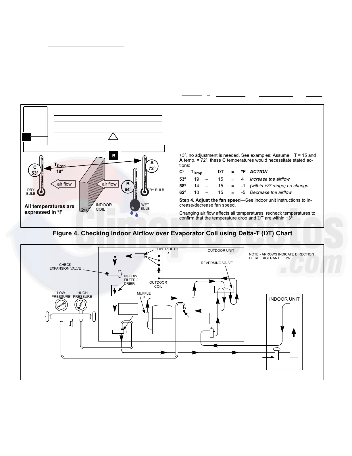
Step 1. Determine the desired DTMeasure entering air tempera-
ture using dry bulb (A) and wet bulb (B). DT is the intersecting value
of A and B in the table (see triangle).
Step 2. Find temperature drop across coilMeasure the coil’s dry
bulb entering and leaving air temperatures (A and C). Temperature
Drop Formula: (T
Drop
) = A minus C.
Step 3. Determine if fan needs adjustmentIf the difference be-
tween the measured T
Drop
and the desired DT (T
Drop
–DT) is within
+3º, no adjustment is needed. See examples: Assume DT = 15 and
A temp. = 72º, these C temperatures would necessitate stated ac-
tions:
Cº T
Drop
– DT = ºF ACTION
53º 19 – 15 = 4 Increase the airflow
58º 14 – 15 = −1 (within +3º range) no change
62º 10 – 15 = −5 Decrease the airflow
Step 4. Adjust the fan speedSee indoor unit instructions to in-
crease/decrease fan speed.
Changing air flow affects all temperatures; recheck temperatures to
confirm that the temperature drop and DT are within +3º.
DT
80 24 24 24 23 23 22 22 22 20 19 18 17 16 15
78 23 23 23 22 22 21 21 20 19 18 17 16 15 14
76 22 22 22 21 21 20 19 19 18 17 16 15 14 13
74 21 21 21 20 19 19 18 17 16 16 15 14 13 12
72 20 20 19 18 17 17 16 15 15 14 13 12 11 10
70 19 19 18 18 17 17 16 15 15 14 13 12 11 10
57 58 59 60 61 62 63 64 65 66 67 68 69 70
Temp.
of air
entering
indoor
coil ºF
INDOOR
COIL
DRY BULBDRY
BULB
WET
BULB
B
T
Drop
19º
A
Dry−bulb
Wet−bulb ºF
A
72º
B
64º
C
53º
air flowair flow
All temperatures are
expressed in ºF
Figure 4. Checking Indoor Airflow over Evaporator Coil using Delta−T (DT) Chart
NOTE − USE GAUGE PORTS ON VAPOR LINE VALVE AND LIQUID VALVE FOR EVACUATING REFRIGERANT
LINES AND INDOOR COIL. USE VAPOR GAUGE PORT TO MEASURE VAPOR PRESSURE DURING
CHARGING.
OUTDOOR
COIL
CHECK
EXPANSION VALVE
BIFLOW
FILTER /
DRIER
TO
HFC−410
A DRUM
LOW
PRESSURE
COMPRESSO
R
REVERSING VALVE
VAPOR
LINE
VALVE
MUFFLE
R
NOTE − ARROWS INDICATE DIRECTION
OF REFRIGERANT FLOW
CHECK EXPANSION VALVE
INDOOR UNIT
OUTDOOR UNIT
LIQUID
SERVICE
PORT
GAUGE
MANIFOLD
DISTRIBUTO
R
INDOOR
COIL
VAPOR
SERVICE
PORT
HUGH
PRESSURE
LIQUID
LINE
VALVE
Figure 5. 13HPX Cooling Cycle (Showing Gauge Manifold Connections)

 Loading...